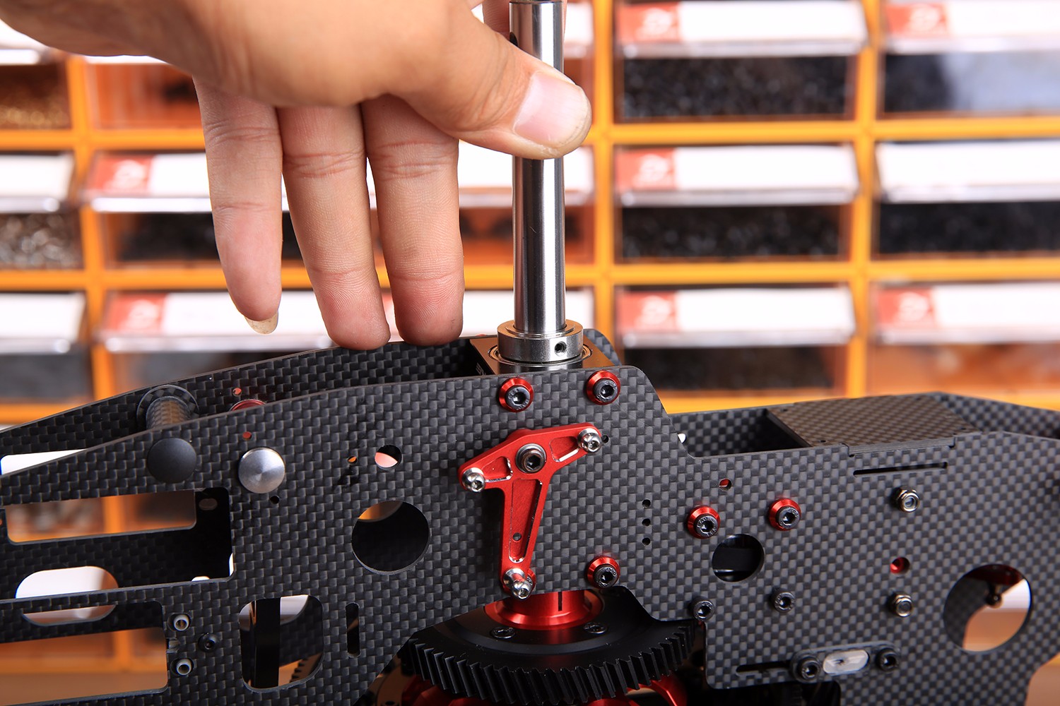
RVE MERAK E750 has been recognized and unanimously praised since its launch, and now the assembly of the body's attention and complete installation process to share with you, I hope it can help you.
A new beginning ~ ~ ~ ~ ~
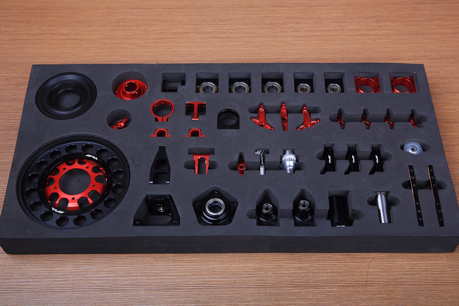
All the spare parts are in accordance with the installation sequence.
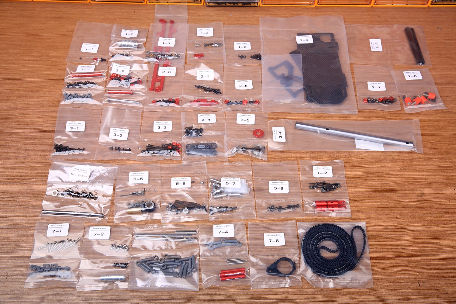
First, 1-1 screws, tail drive bearing *2, front timing belt pulley and tail drive pinion are provided.
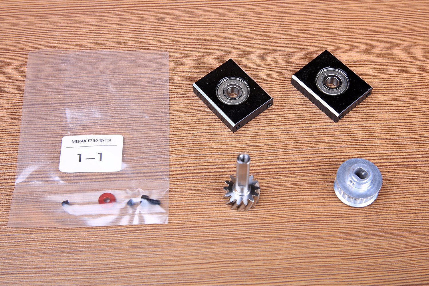
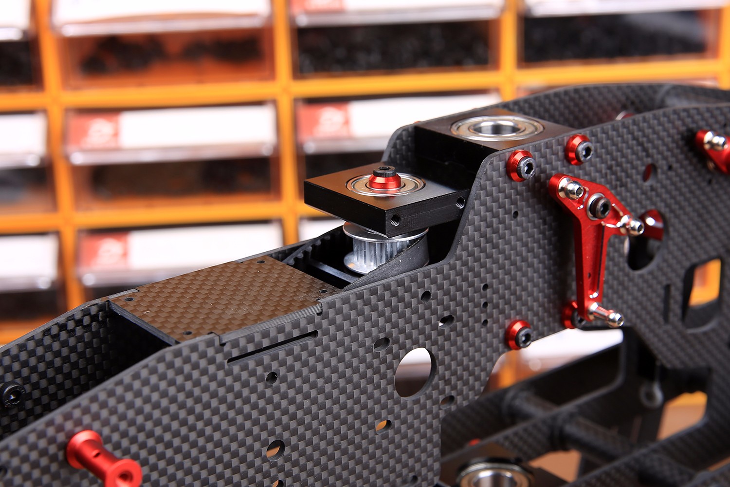
First, drive the small tooth into the bearing seat, please install according to the picture below, pay attention to the reverse side of the bearing block.
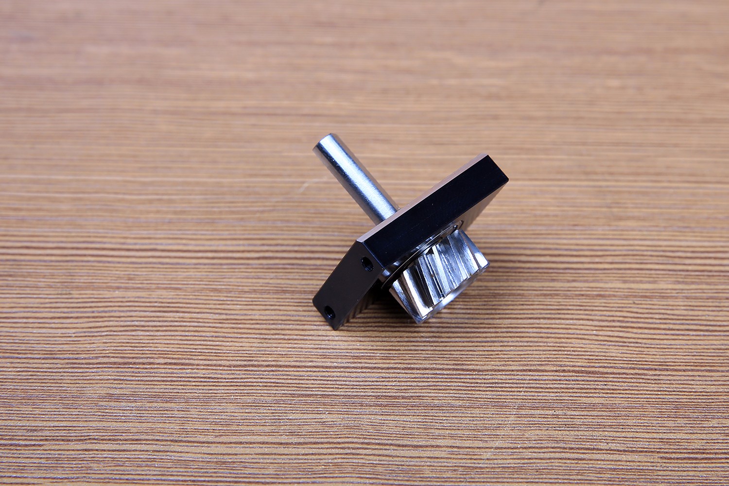
The front drive belt pulley is sleeved on the gear shaft. Attention should be paid to the directivity and the part with the top wire should be upward.
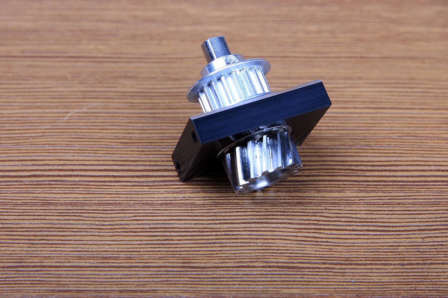
Apply a small amount of medium strength screws to the top wire. Remember not to overdo it.
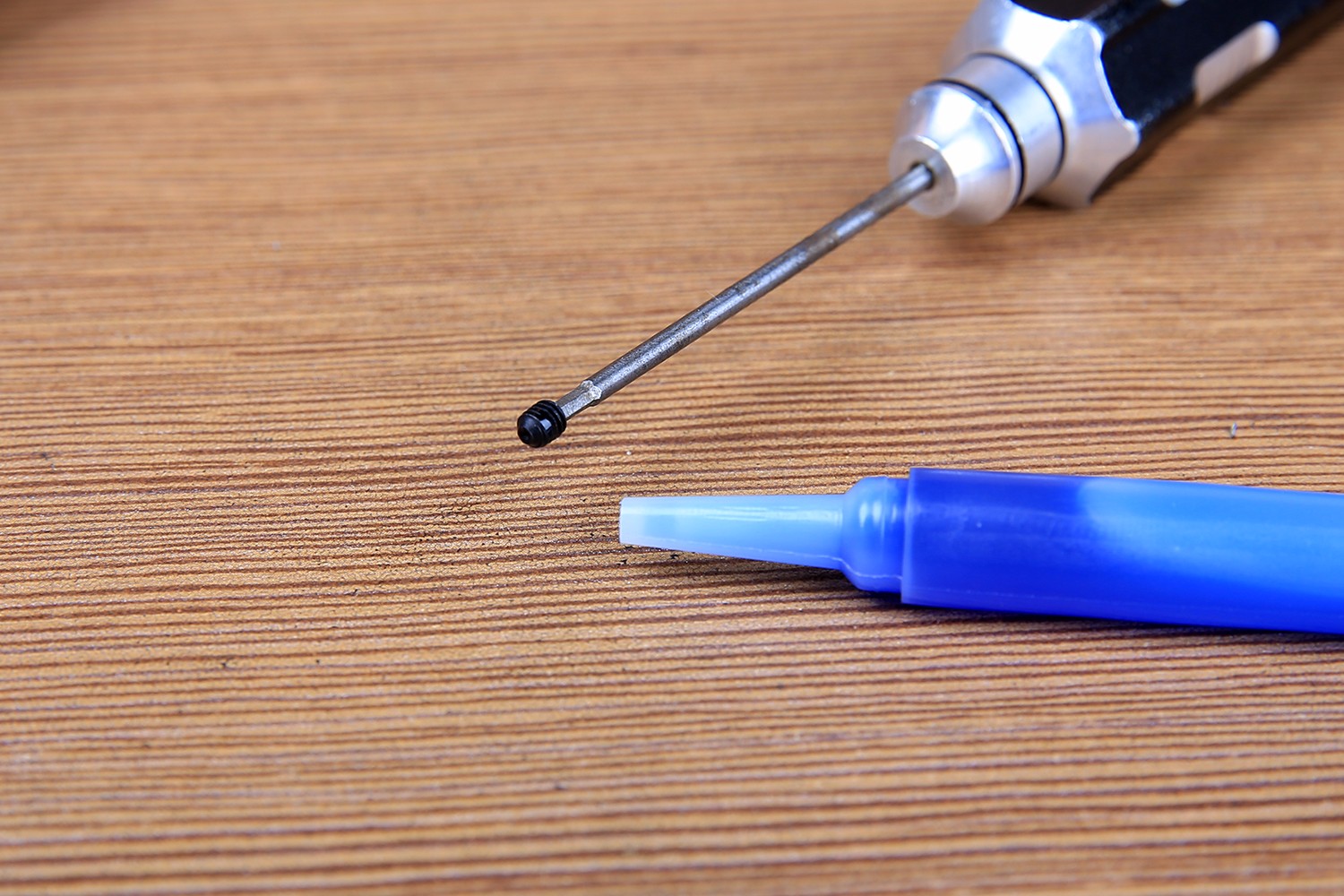
Before tightening the top wire, the synchronous pulley should be tightened down slightly and then tightened, and the two top wires should be tightened repeatedly in turn to avoid dislocation.
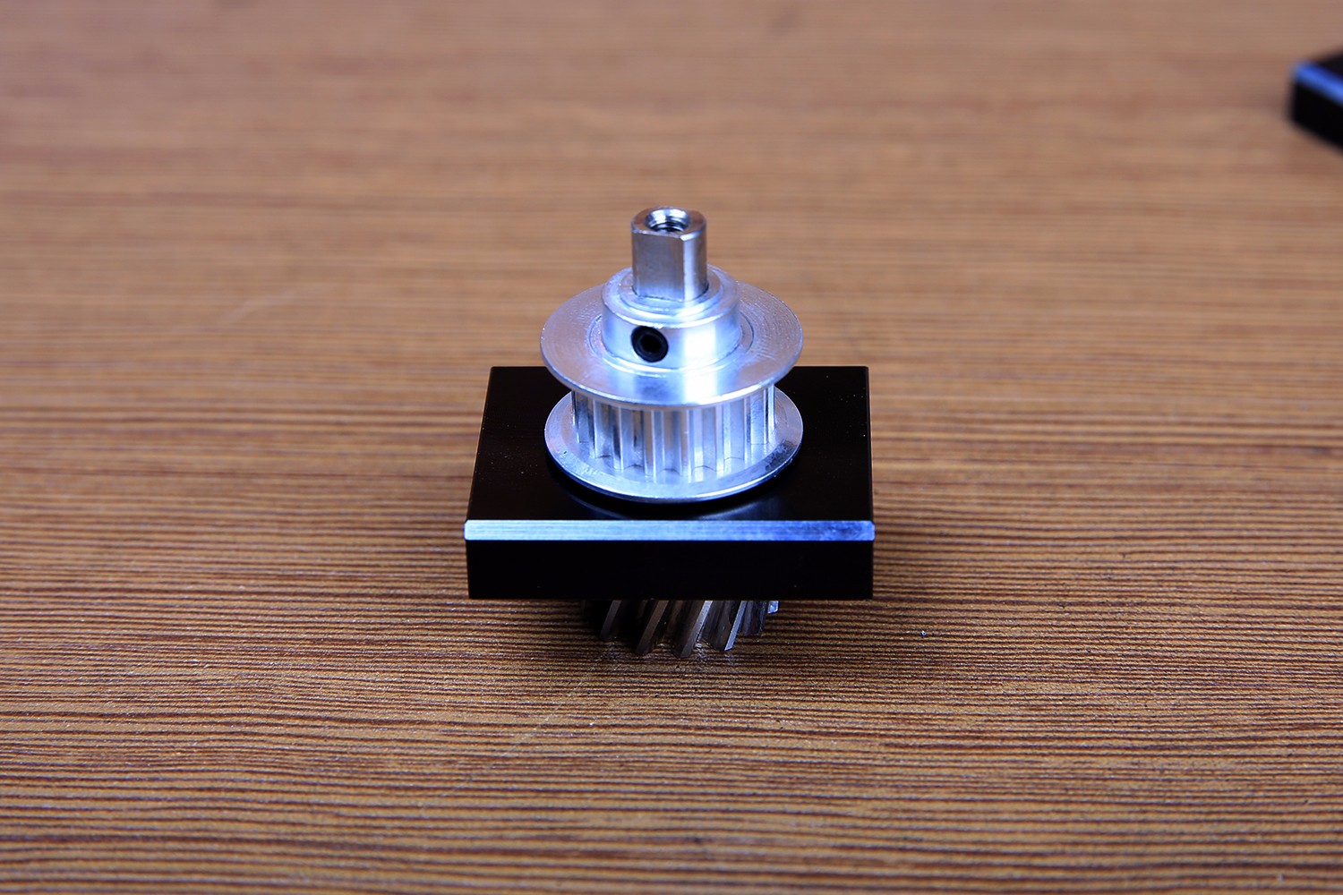
When you install another bearing seat, you should also pay attention to the direction, then tighten the top fixing screw.
Note: the side of the bearing housing has a bevel angle toward the synchronous pulley.
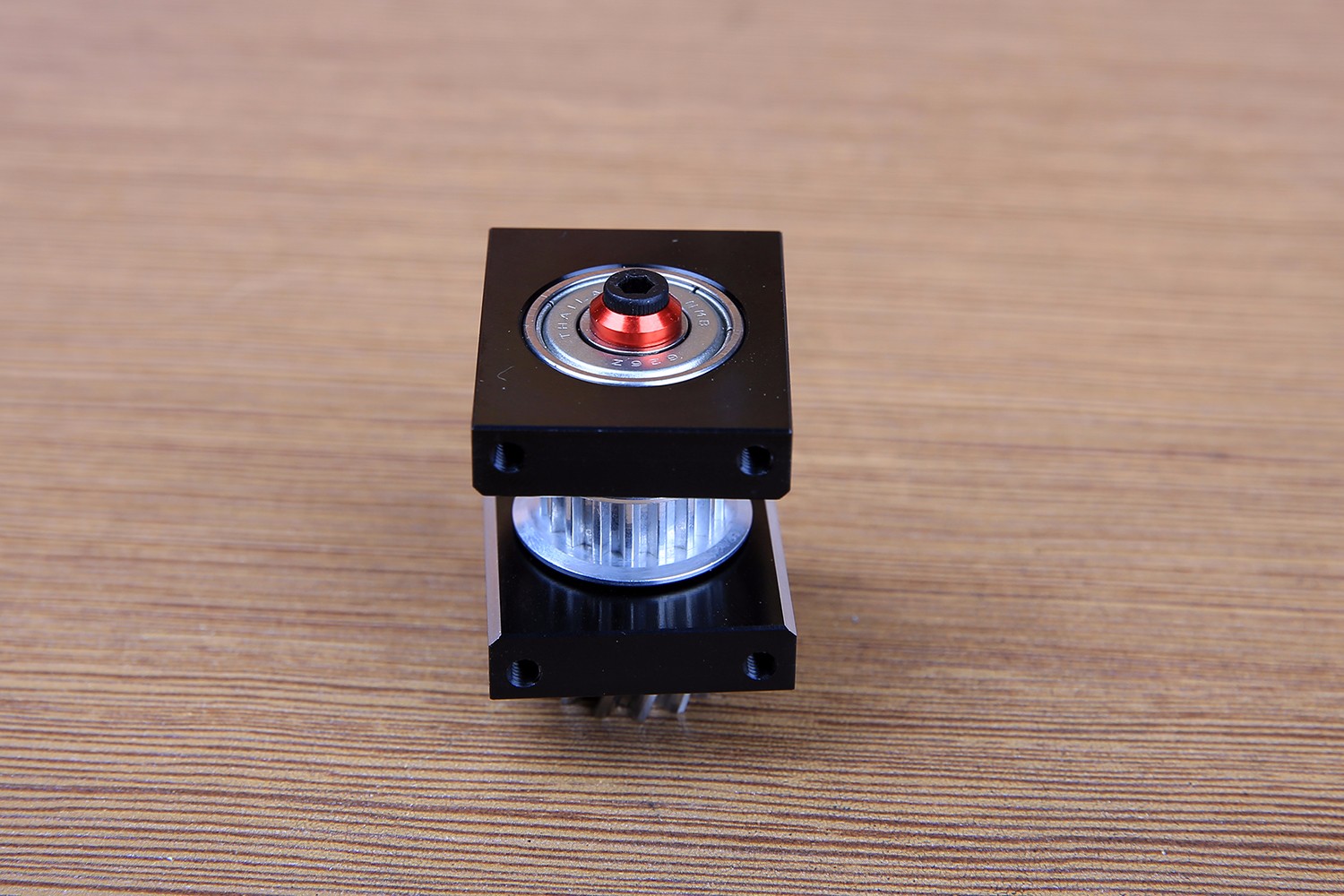
Take out 1-2 screws and motor mounting base. The motor 6MM 6MM shaft can be installed.
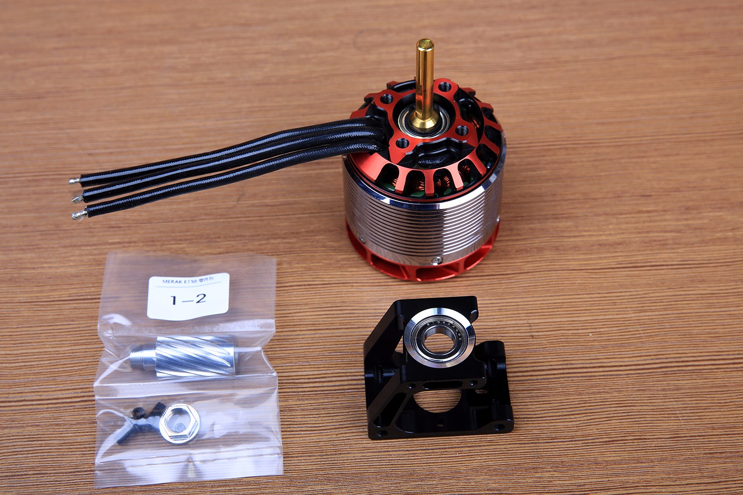
Take out the motor teeth and install them in the motor mounting base, with a little green screw glue between the teeth and bearings.
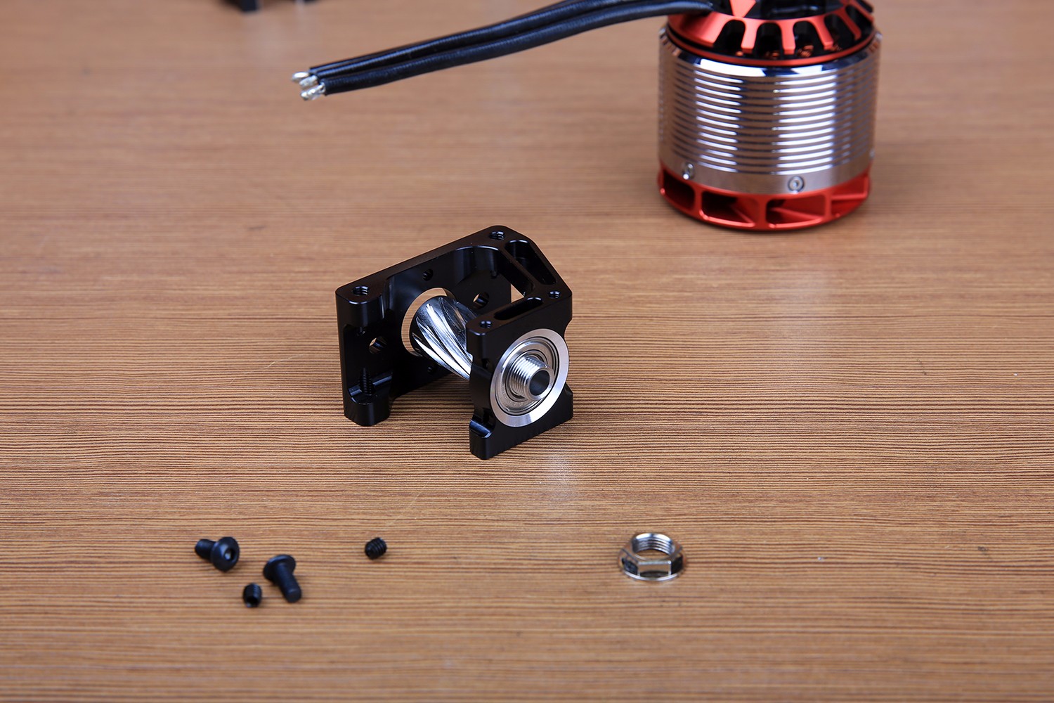
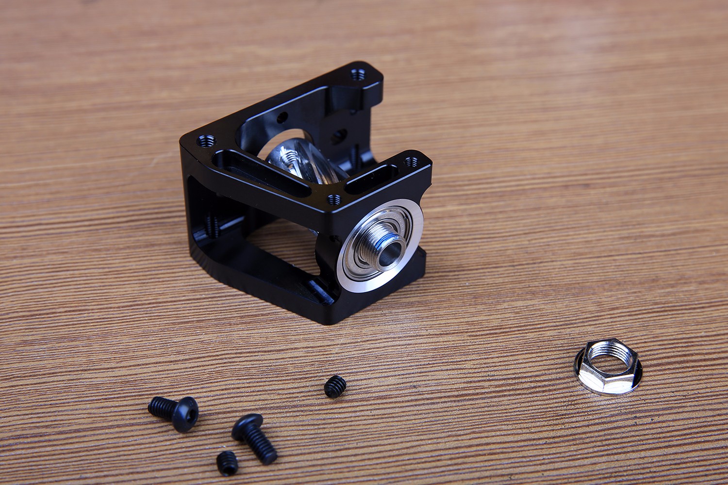
Tighten motor teeth fixing screws. The top thread hits the strength of the screw glue.
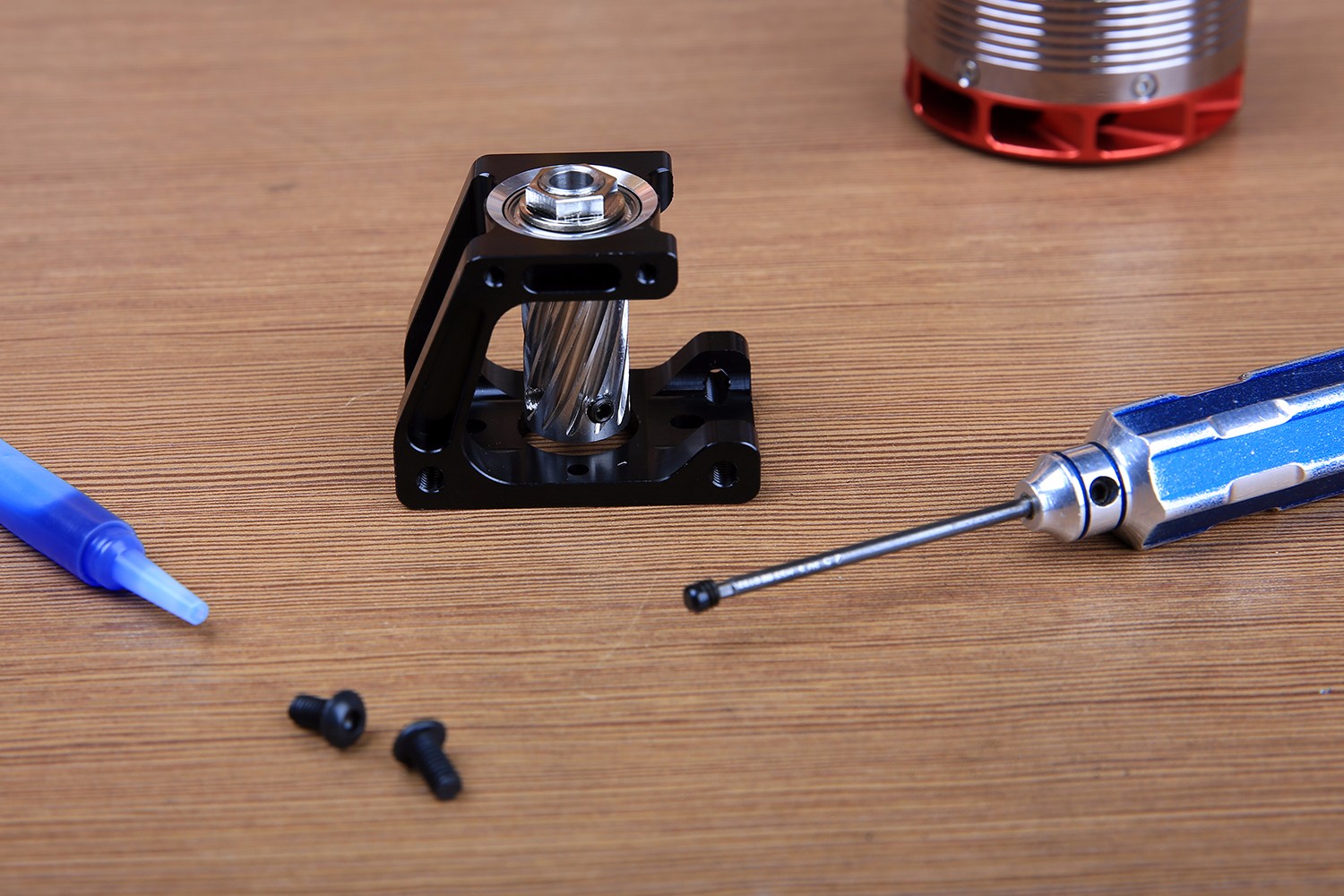
Fix the motor seat with M4 half round head screw.
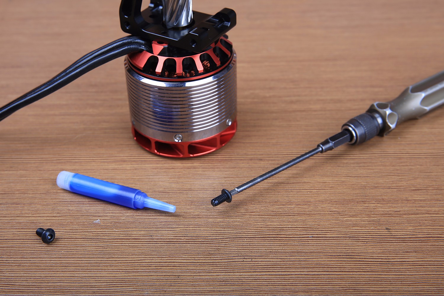
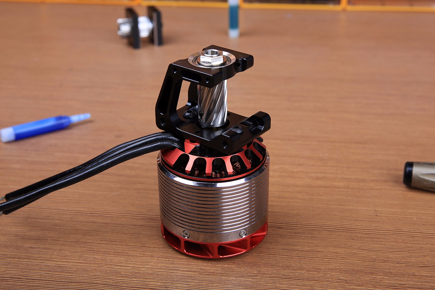
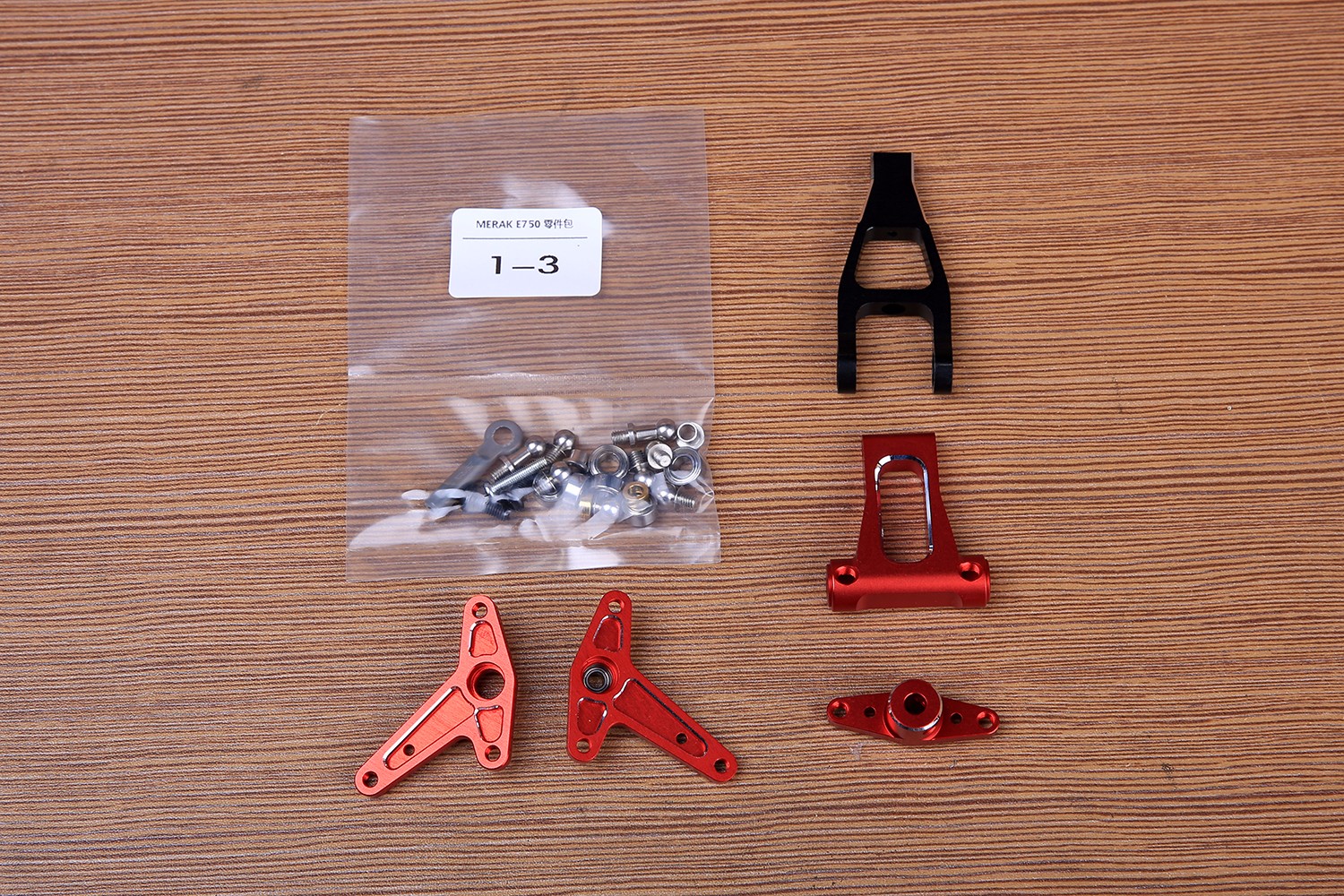
Next, take out the 1-3 part package and the metal parts shown in the picture.
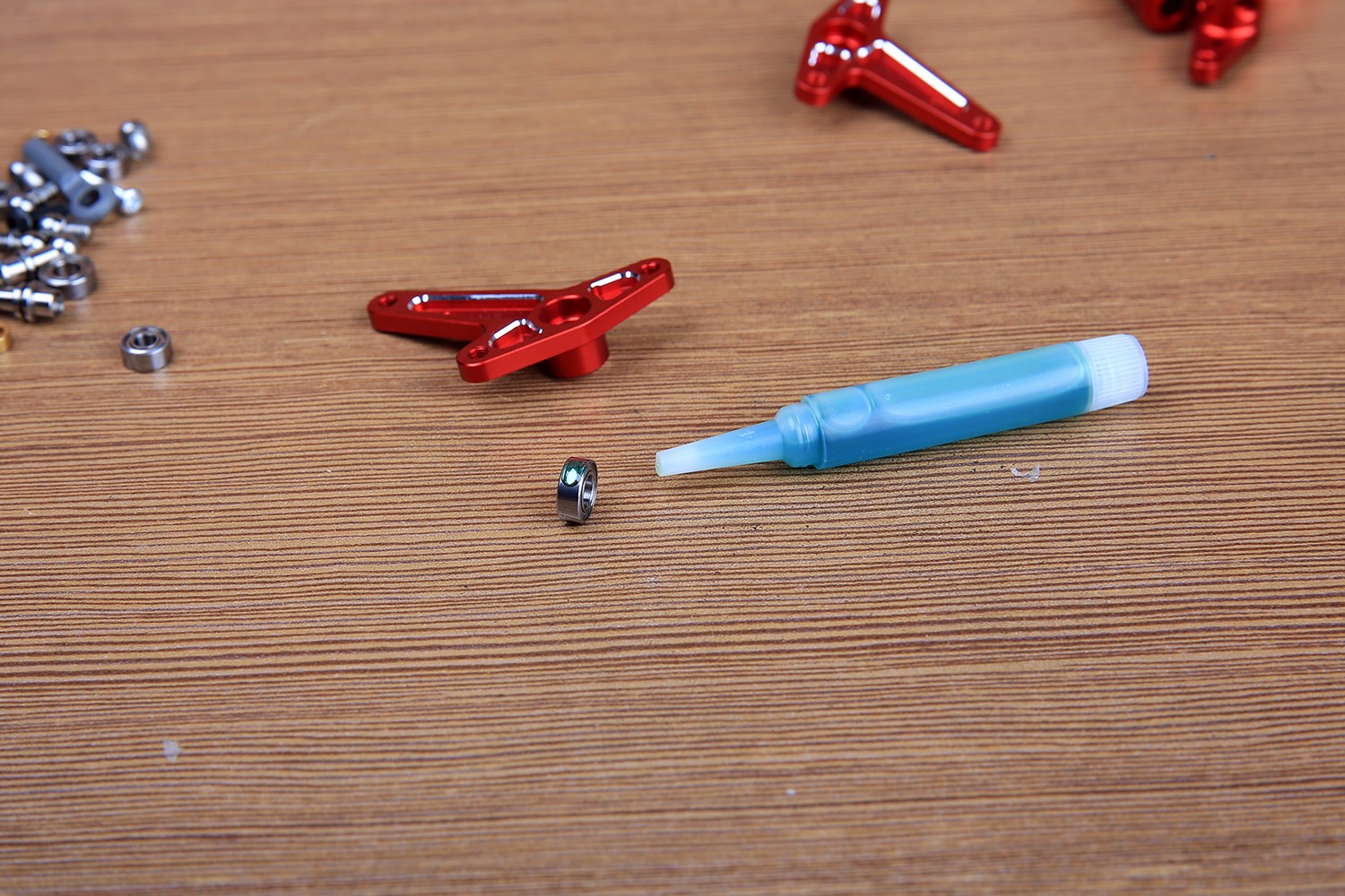
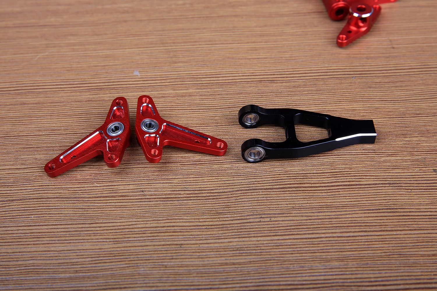
First install the bearing on the rocker arm, and each bearing outer circle is coated with green screws. Attention should be applied evenly to the outer wall of the bearing.
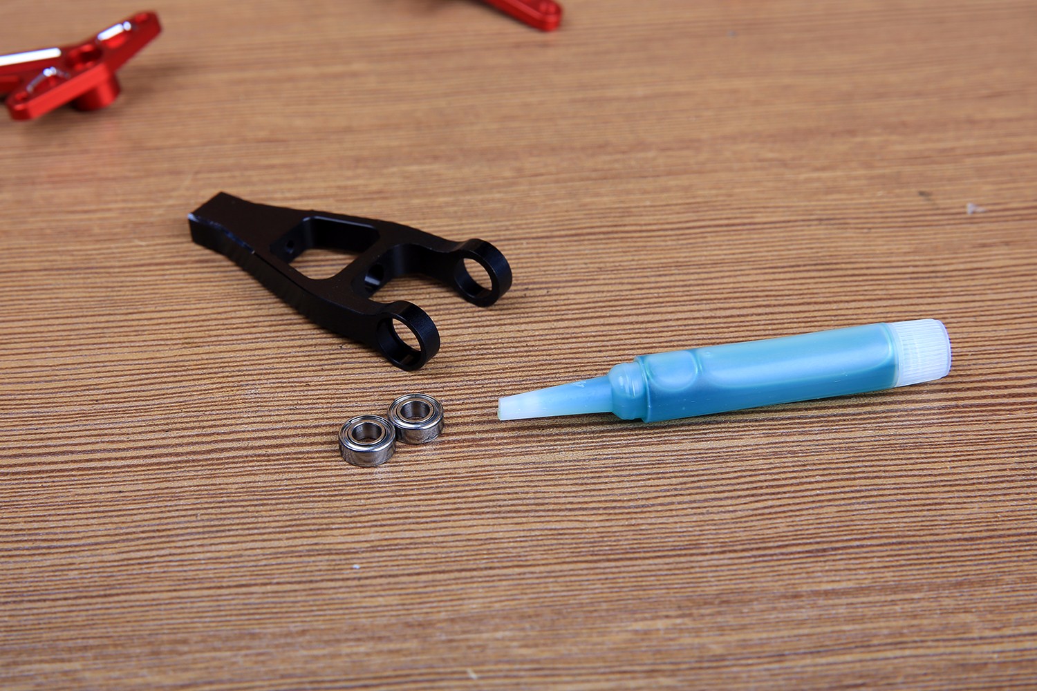
The bearing of the lifting arm is slightly larger than that of the inner hole 4mm, and is also fixed with green screws.
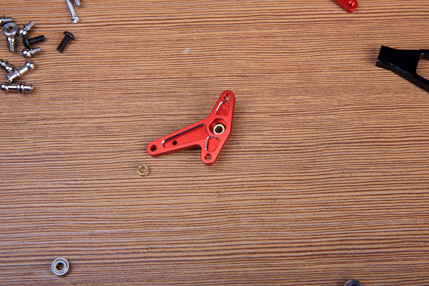
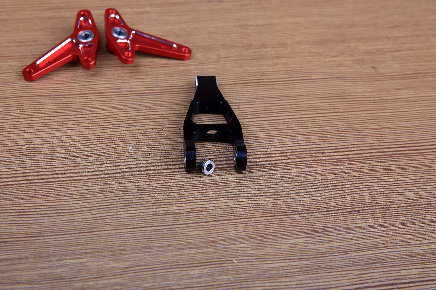
Pay attention here! Triangle control rocker two bearings to install a copper sleeve (thick thickness), do not forget!
The lifting arm has two stainless steel sleeves to fit the installation. Please note that it is installed from inside to outside.
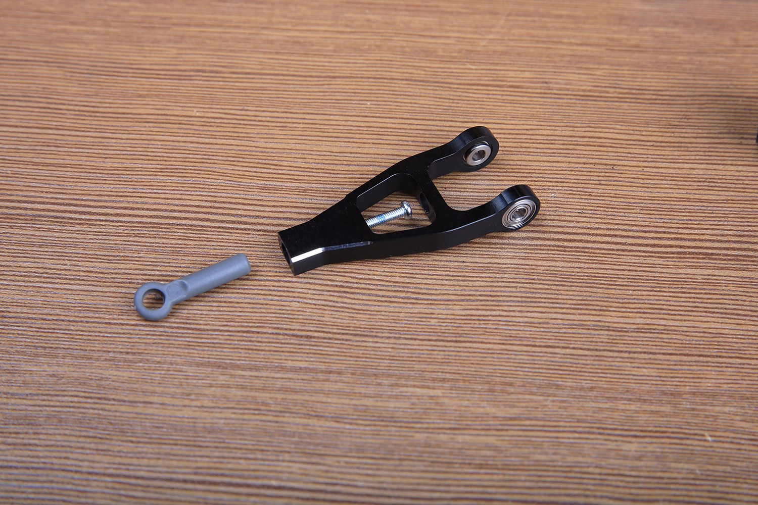
The ball button on the top is fixed with M2.3 screws.
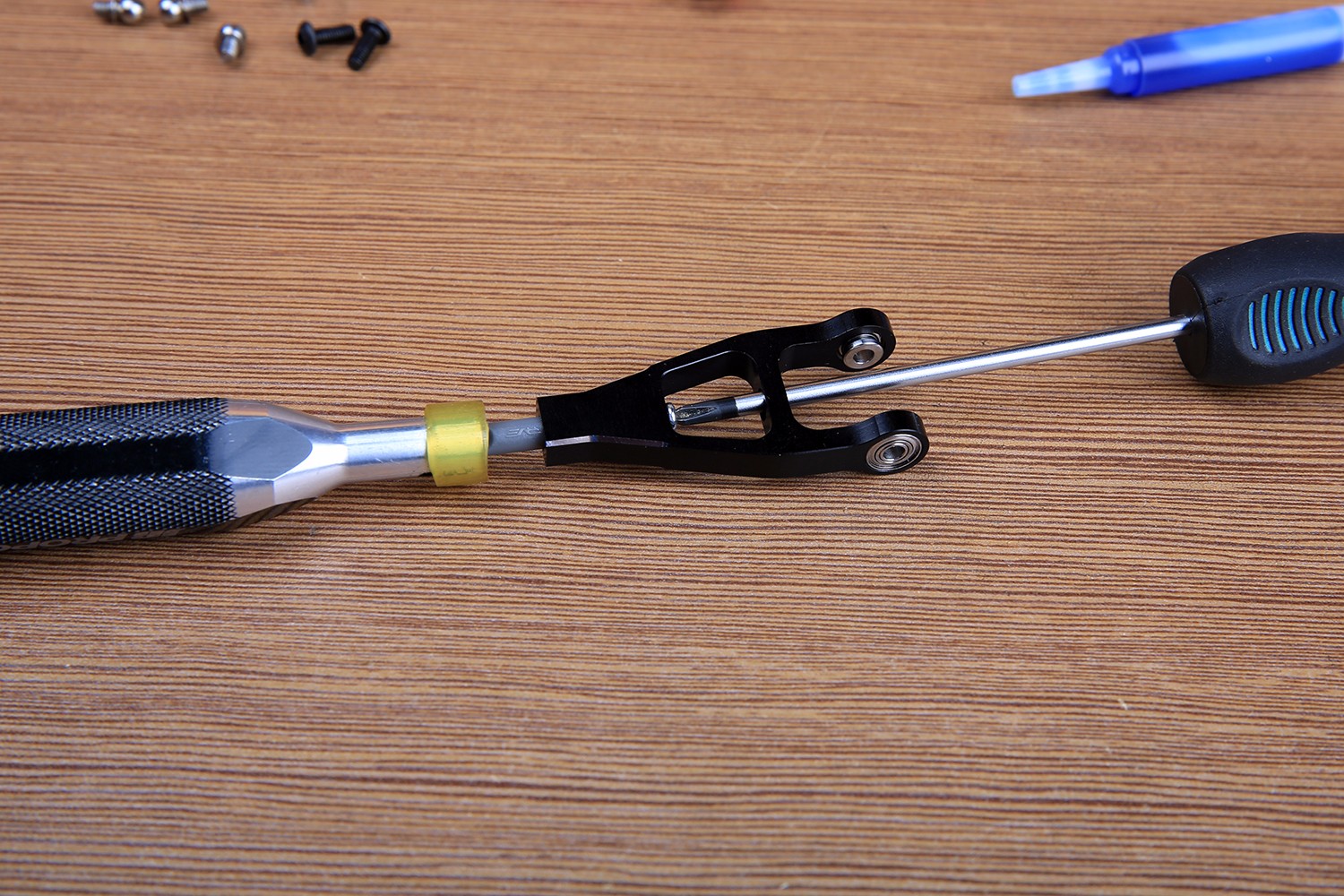
Find out the pedestal is fixed with six angle screws in the M3*8 half round head. A small amount of screw glue will stick to the bearing sleeve.
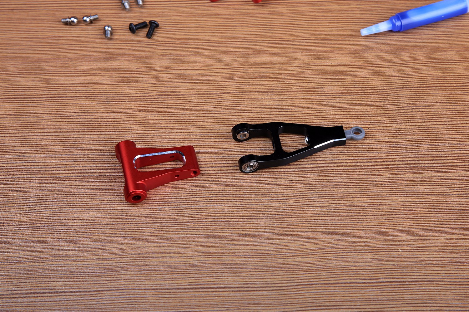
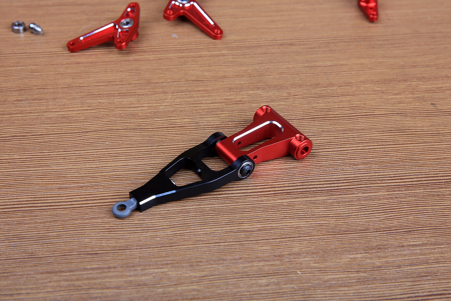
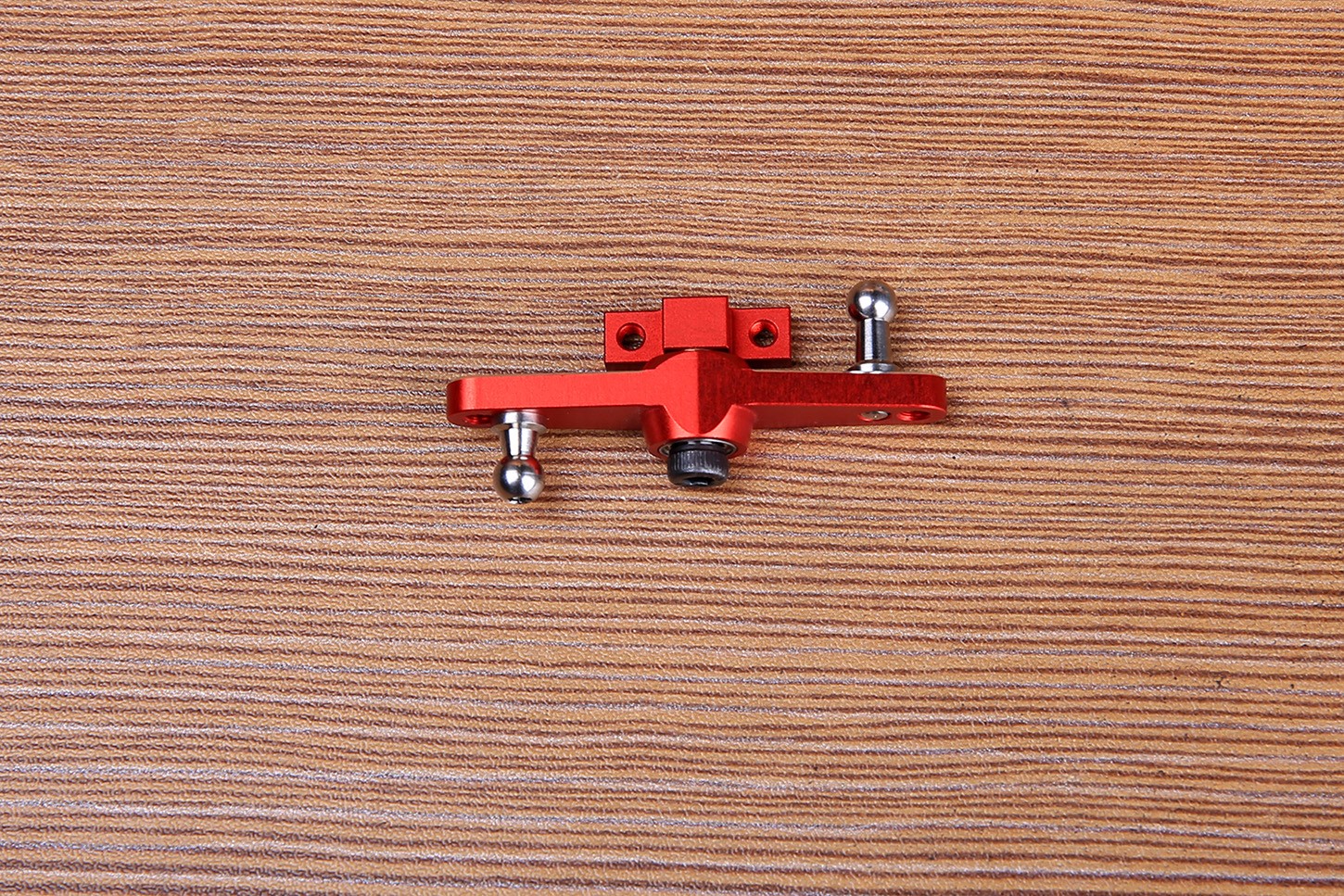
The triangle rocker arm installs the good ball head. When installing, please pay attention to the difference between the ball head length and the installation position.

Next, take out 1-4 screws to assemble the rudder tie rod and change the rocker arm.
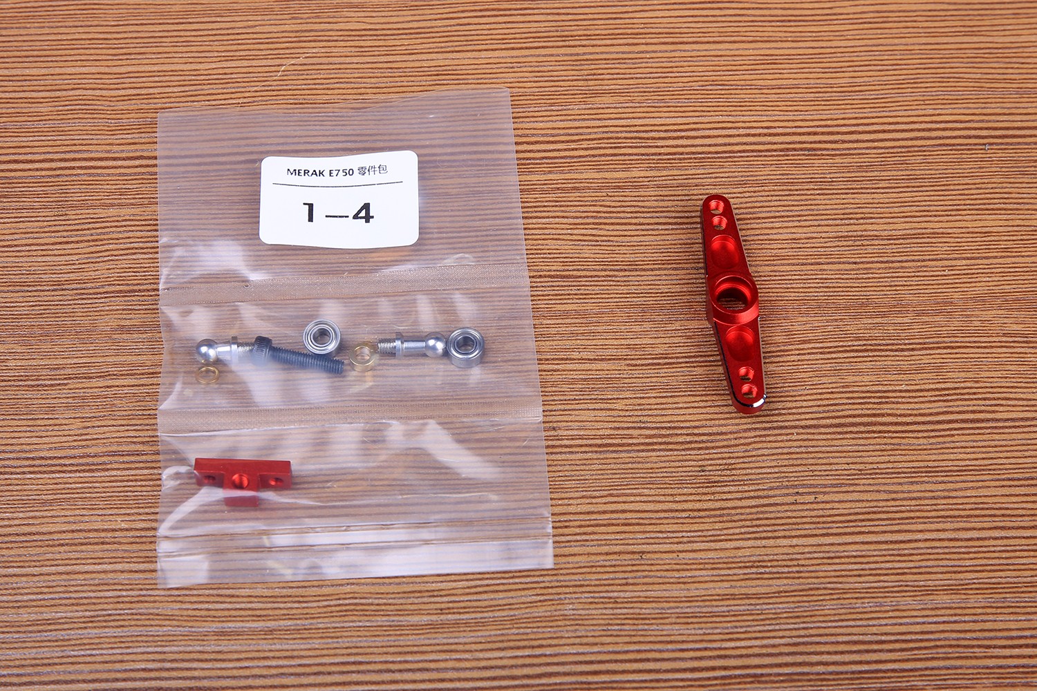
The first step is to install bearings, in the same way as the triangular rocker arm mentioned earlier. Don't forget the copper sleeve in the middle. There is also a very small copper gasket in this screwbag which is also useful. Please assemble this part set in the order shown below.
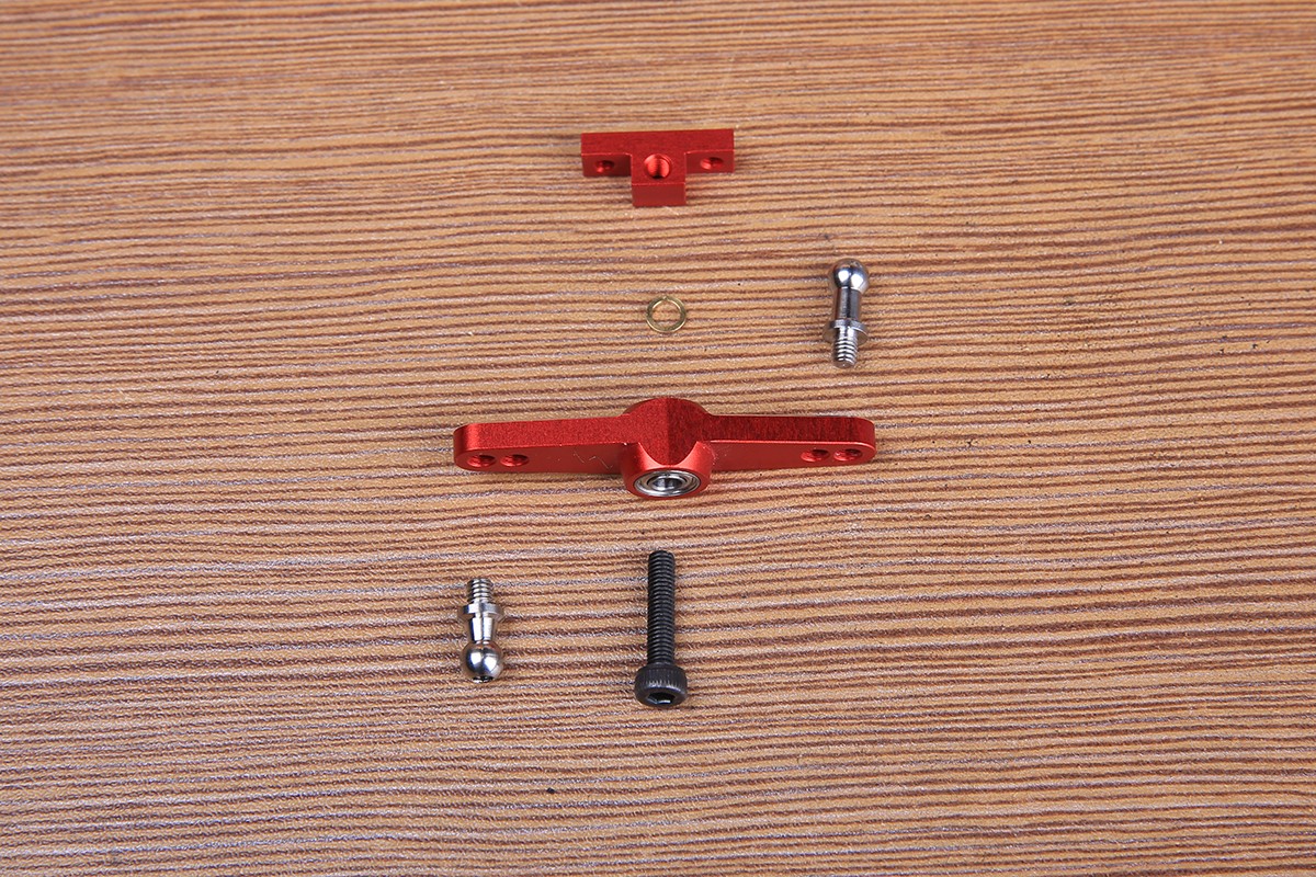
This yellow copper gasket should be installed here, and the ball head should be installed in the inner hole.

For the assembled rocker arm group, please pay attention to the length and position of the ball head.
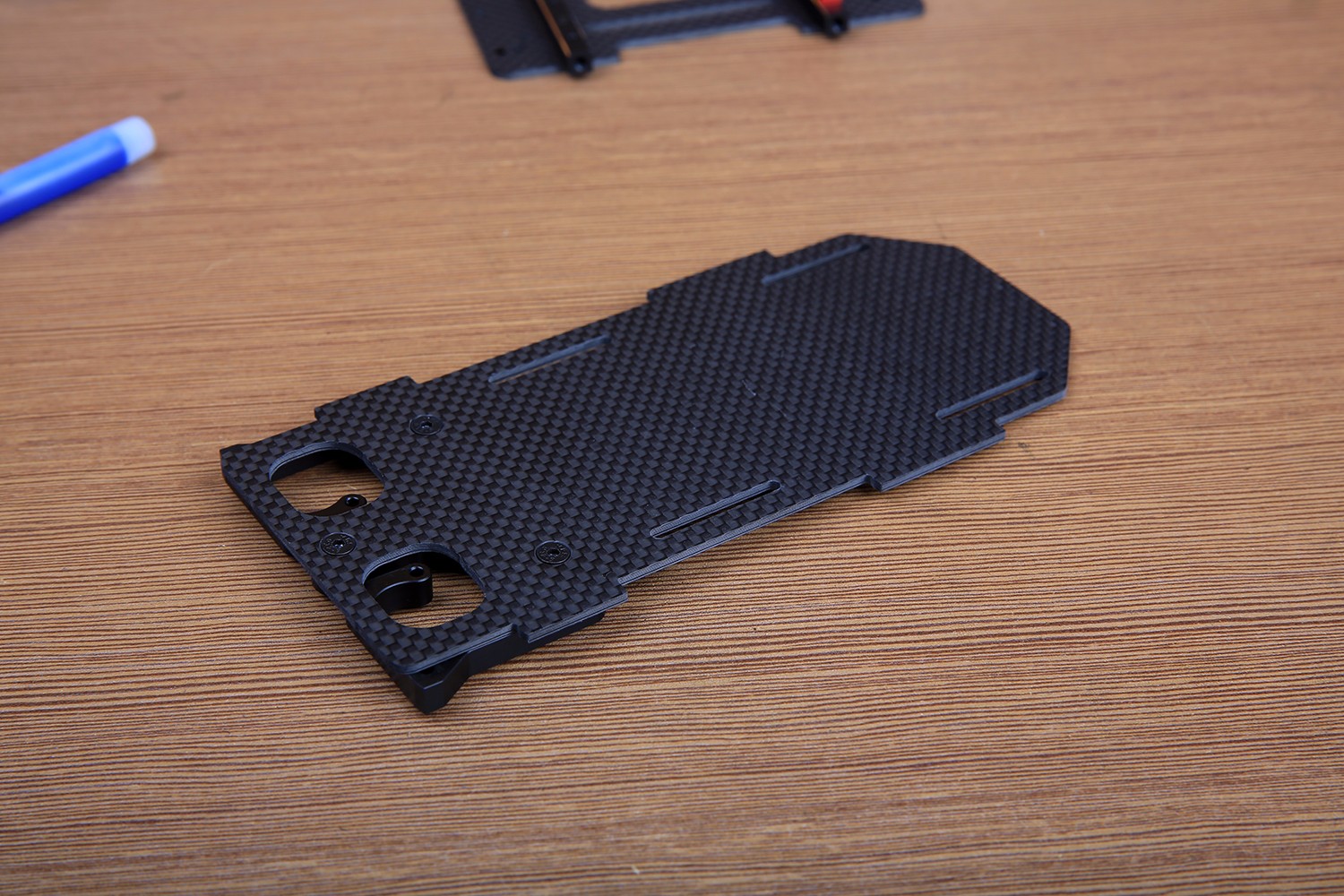
Take out 1-6 and 2-6 accessory kit below. This part is electrically adjustable mounting panel and battery panel.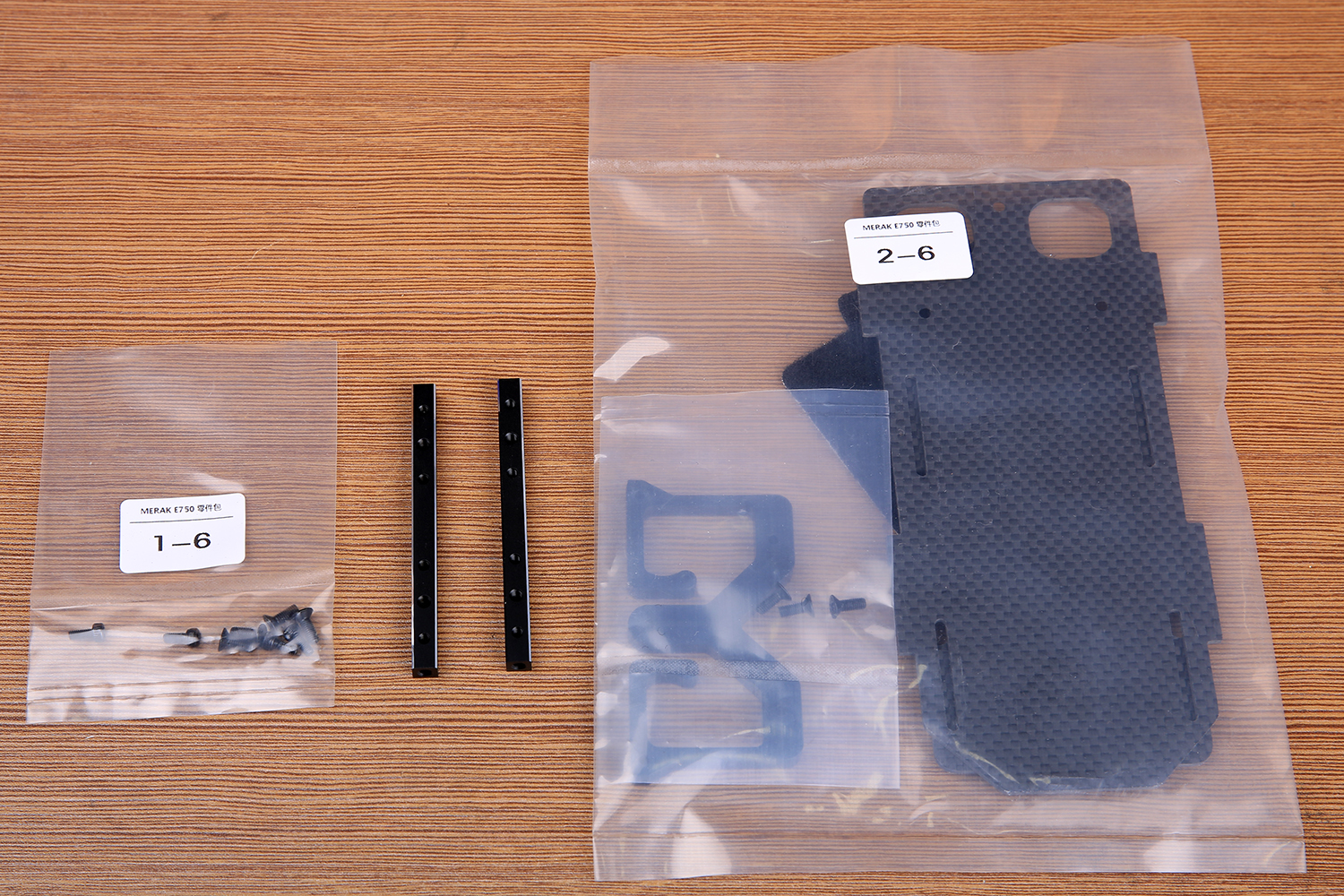 Pay attention to the high bright surface of the installation column without carbon plate. The red battery plug mounting base can be matched with the XT150 plug to facilitate power battery energization.
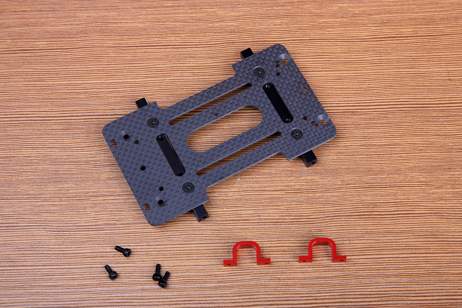
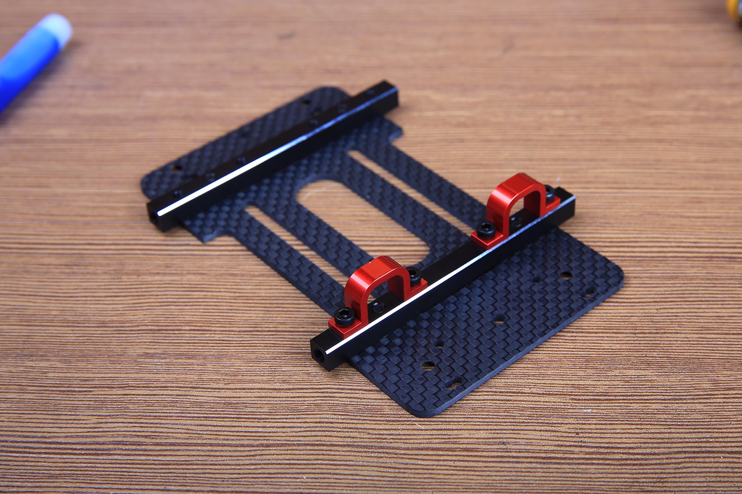
The battery panels and battery boards are fasten with three M3*8 countersunk screws.
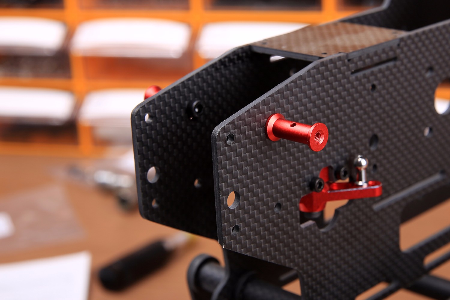
Next, we will start assembling the fuselage part, and first take out the integrated side panel and the 2-1 accessories package. First, install the steering gear mounting base and the housing fixed column.
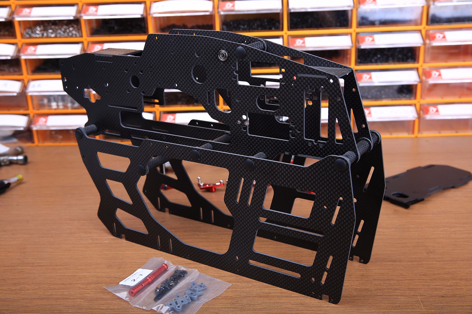
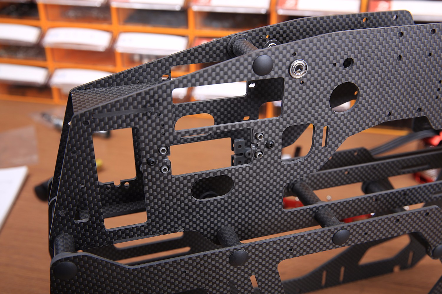
Fix the steering wheel mounting base to the side panel with the M2.5*4 half round head screw.
The left and right two pieces, pay attention to screws do not lock, because later also need to fine tune the servo position.
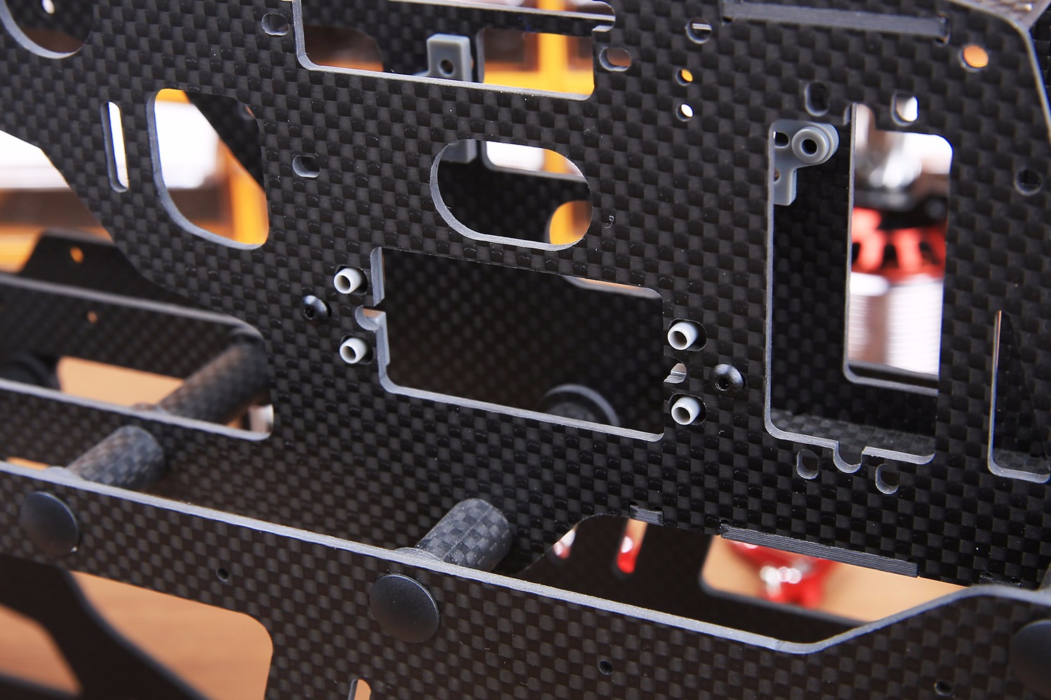
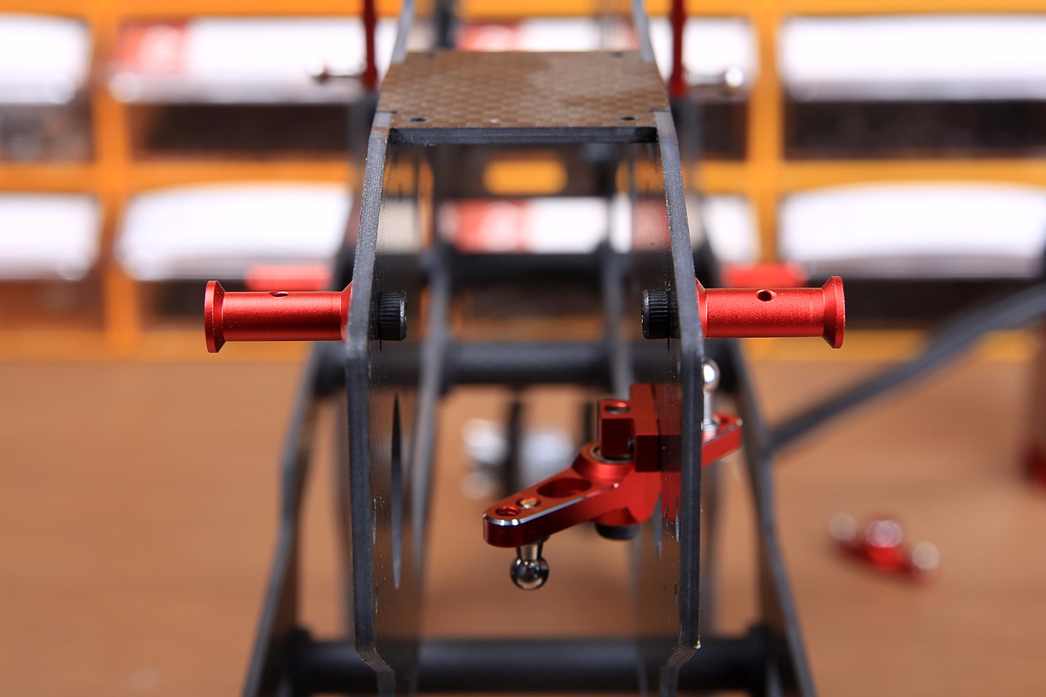
The front housing fixed column uses the long six M3*8 screws with a half round head.
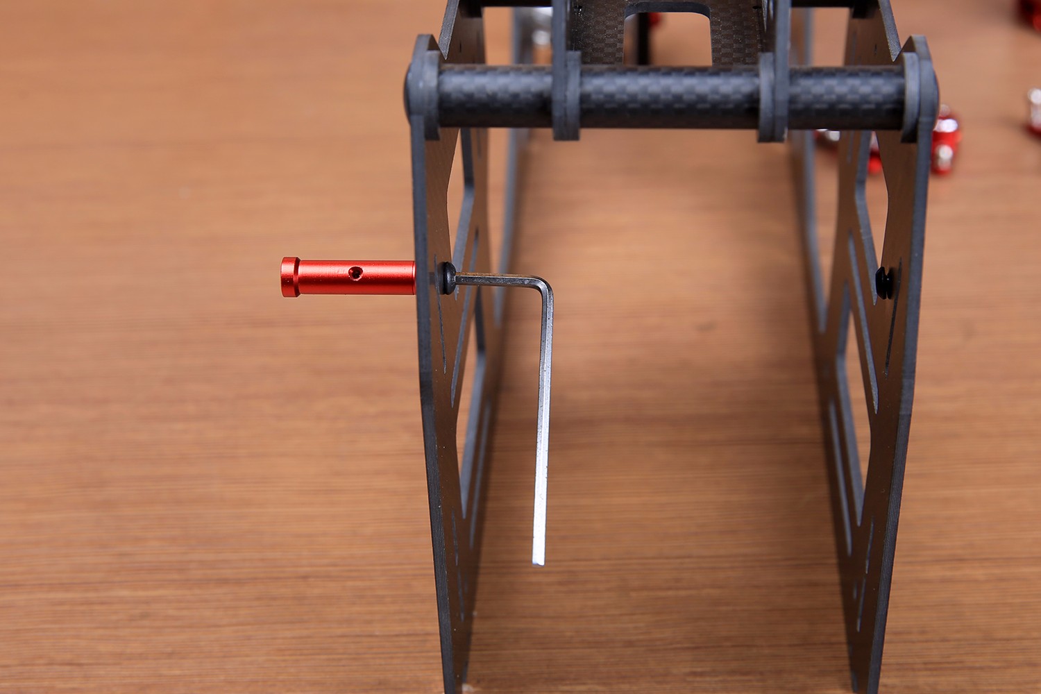
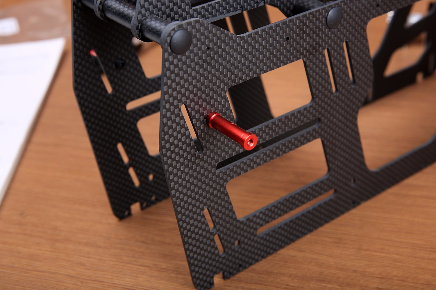
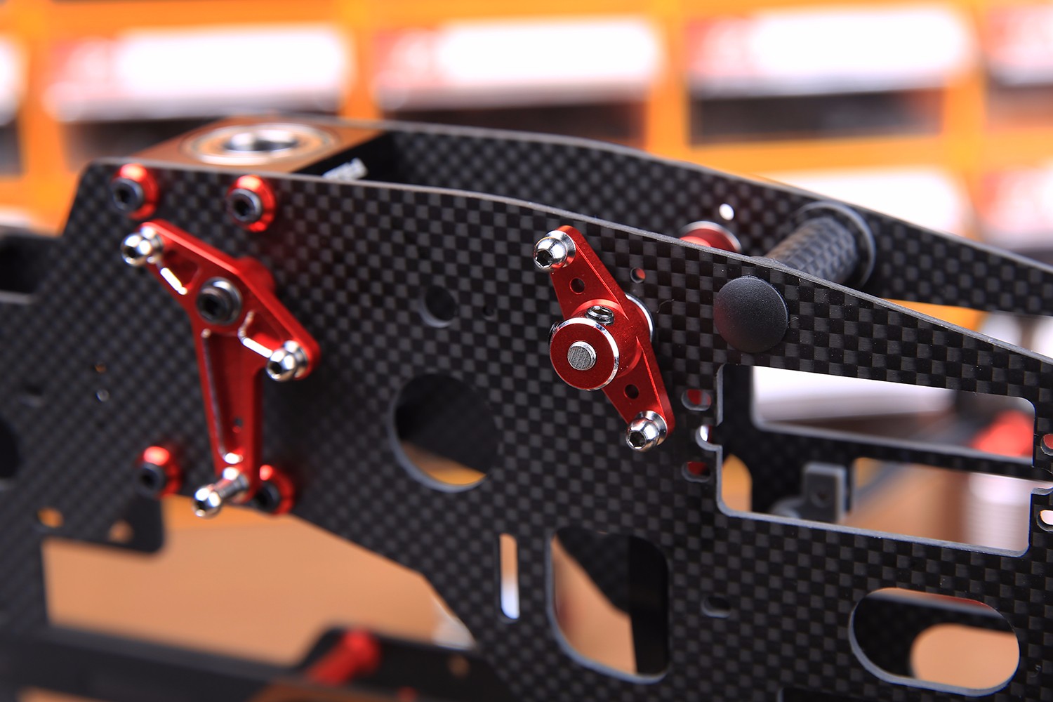
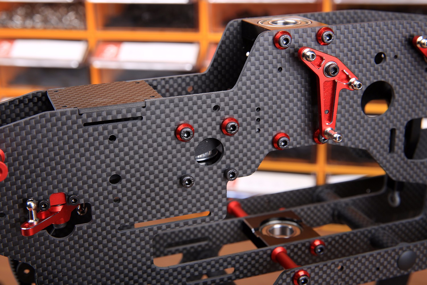
Next, take out the triangle rocker that we have installed, and fix it to the side board with the inner six angle screw of M3*15. Pay attention to the shim between the side plate and the rocker arm. Don't forget to install it.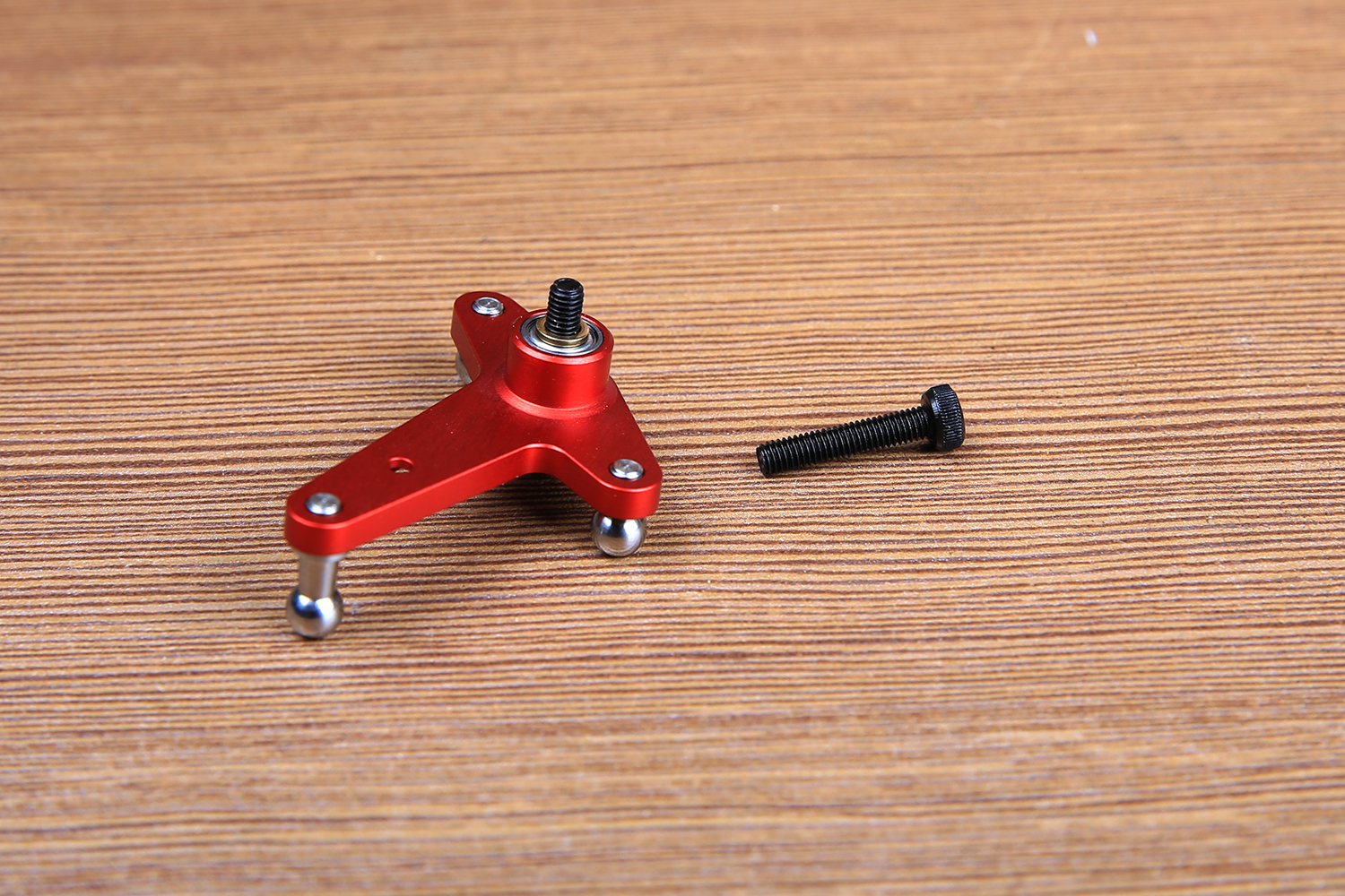
Especially:
Keep your rocker arm around, please be careful!
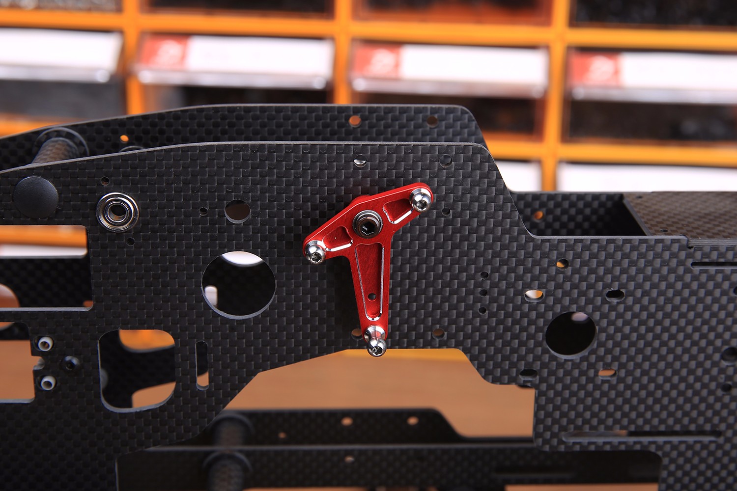
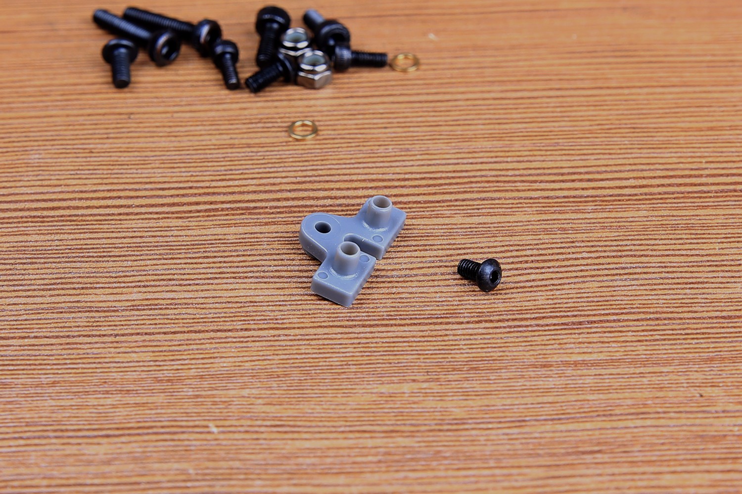
Next, we use the inner six angle screws of M2.5*6 to fix the tail rudder tie rod to the side plate. Note here the installation direction of the T-seat, please see the following figure: Also note that the longer ball head is facing the lateral plate.
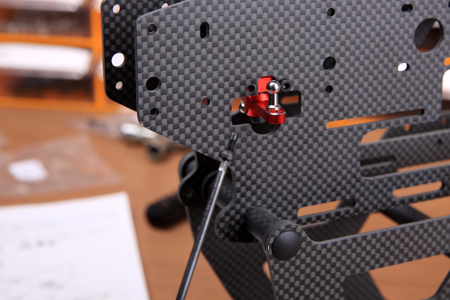
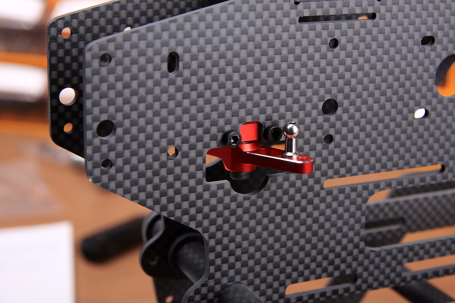
Please pay attention to the direction of mounting base.
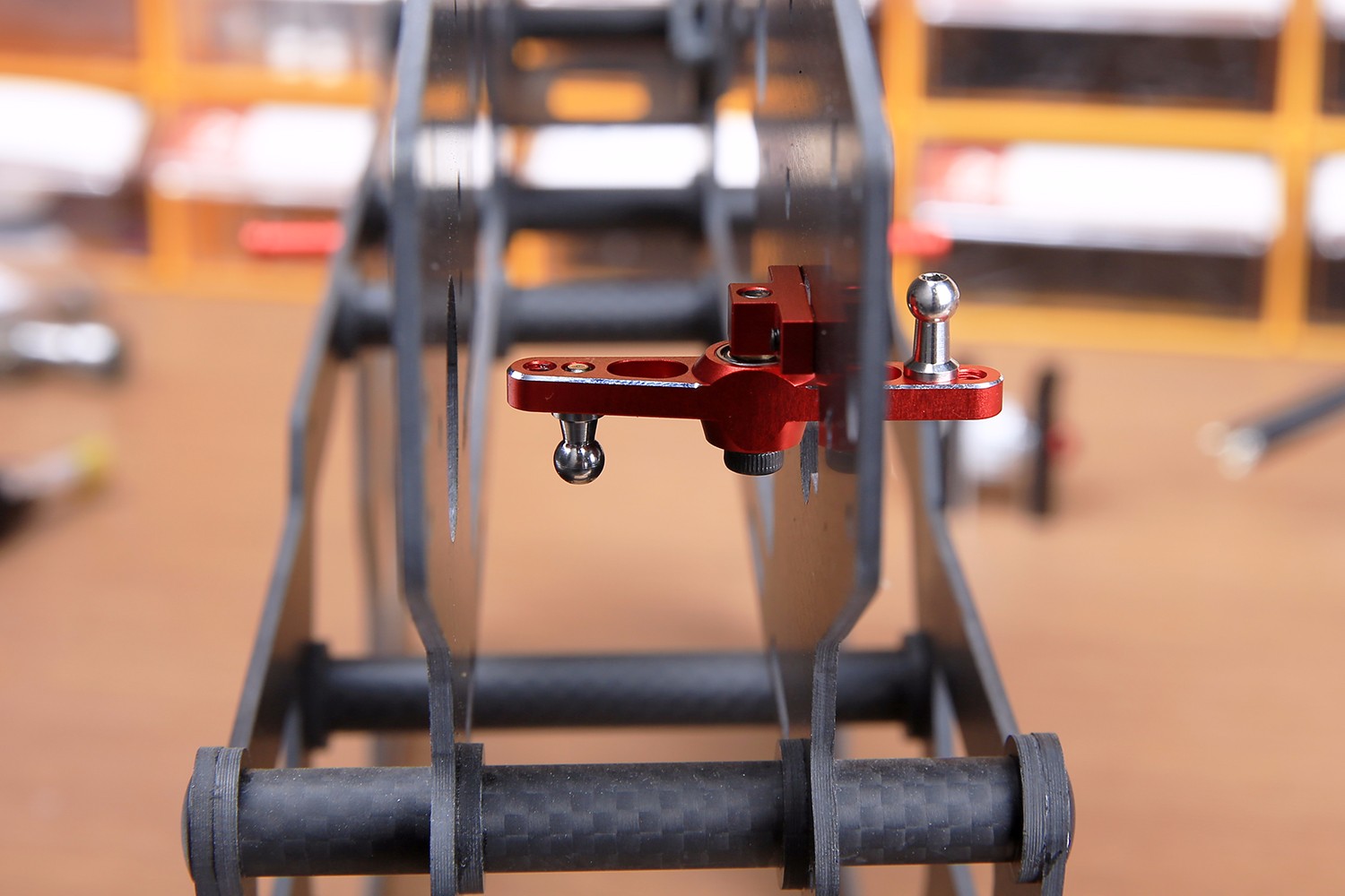
We're going to install the rear housing retainer, where the holes are adjustable from top to bottom, and the mounting position can be carefully adjusted.
Next we take out the 2-2 part package and the spindle bearing block.
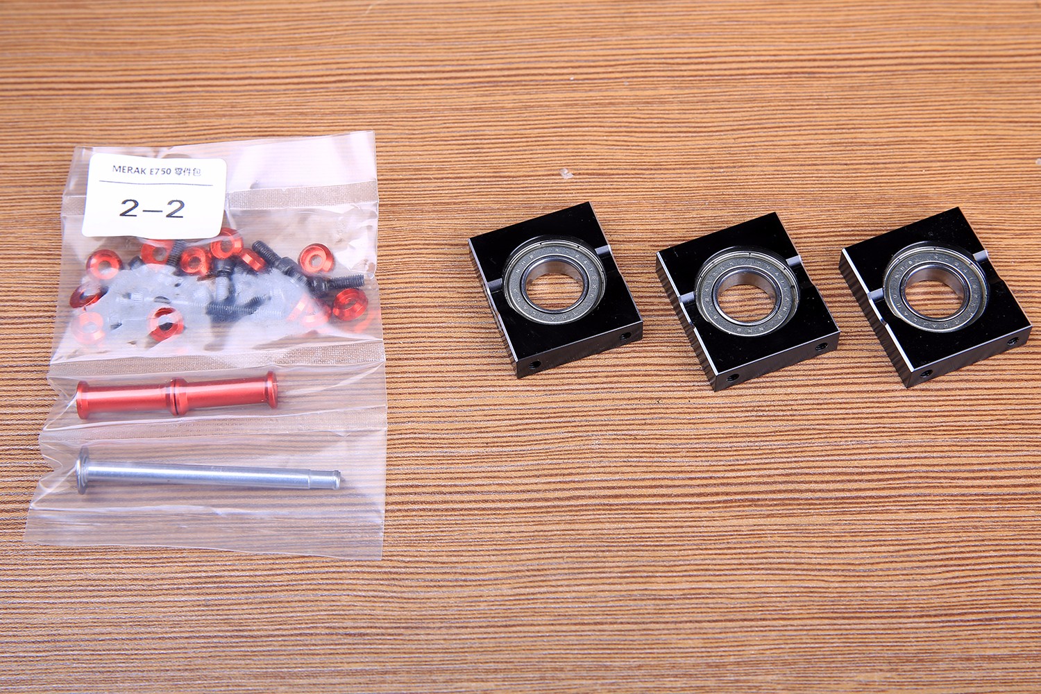
Please pay attention to the direction of installation. The upper bearing has a grooved side downward and fixed with M3*8 screws.
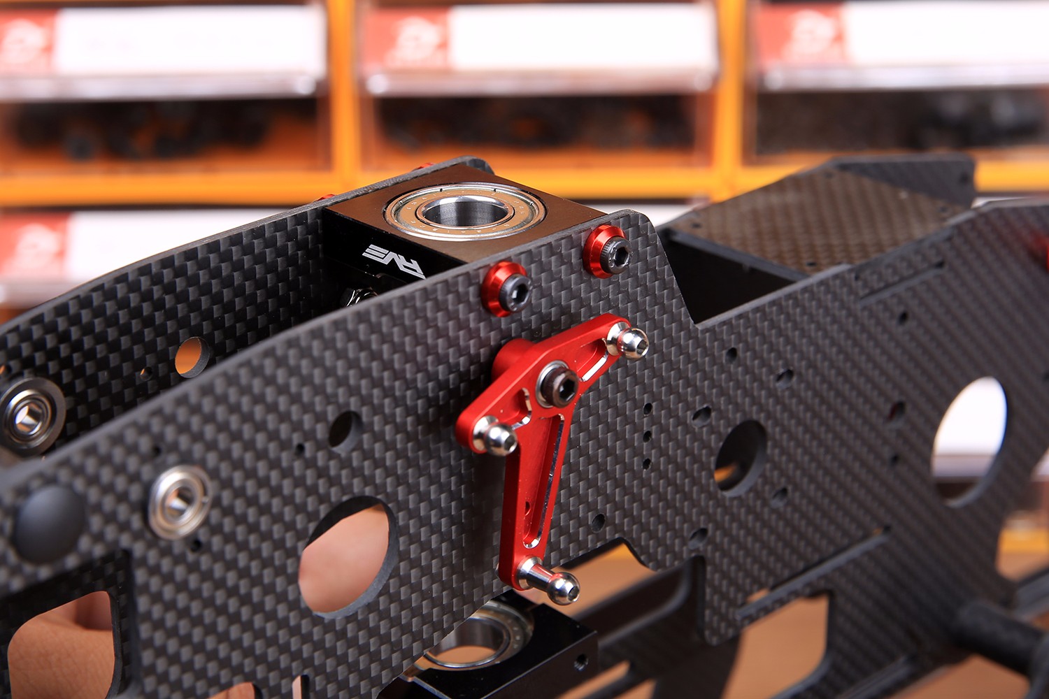
The middle bearing groove is facing upward.
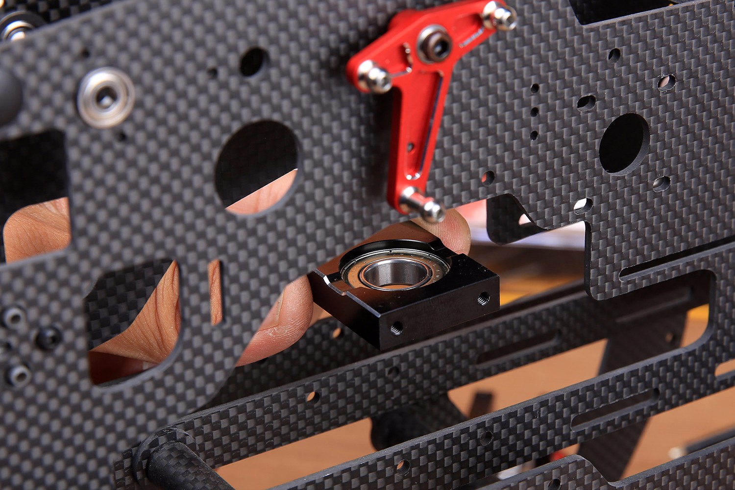
The bottom bearing groove is facing up. Please do not install the reverse. Attention should be paid to the rear fixed position of the body with M3 * 30 screws with aluminum support column to fix, the front hole with M3 * 8 screws fixed.
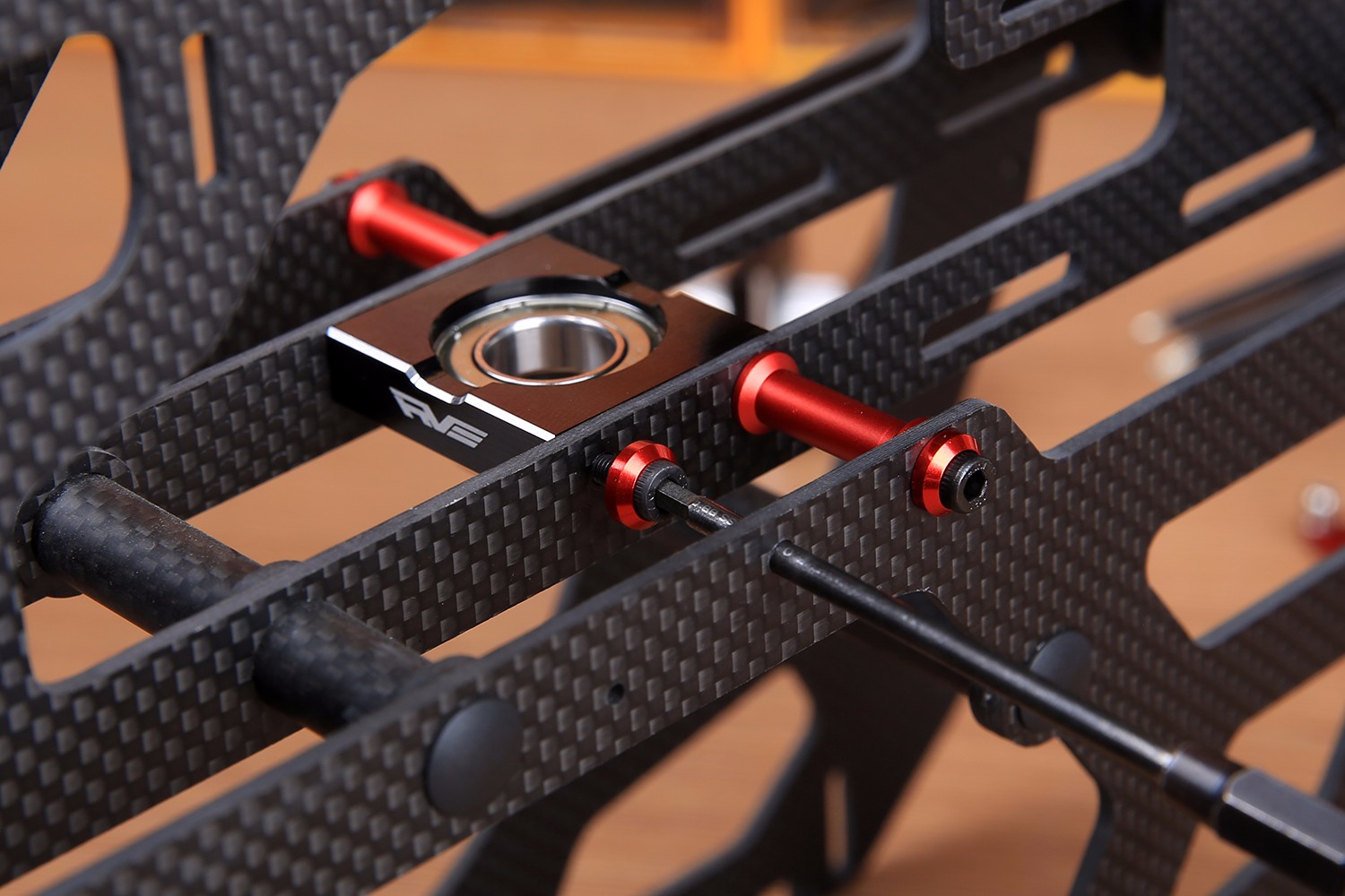
Three bearing blocks are installed.
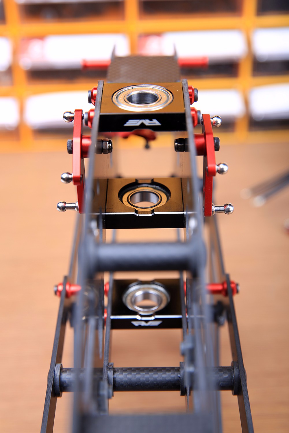
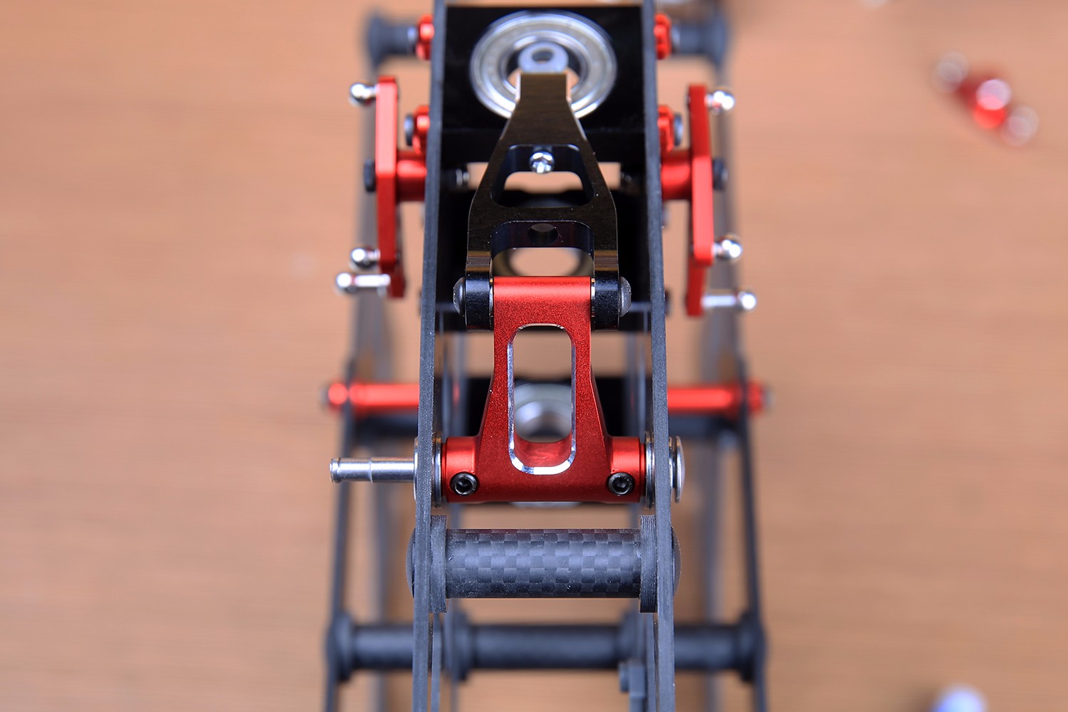
Then the elevator control rocker arm is also installed, here do not need to tighten, later installation of the steering gear to adjust accurately.
If you are a good choice to win 130-200A or KONTRONIK160-200A, our installation board has reserved a fixed hole for electrical adjustment, can be directly fixed on the board, very convenient.
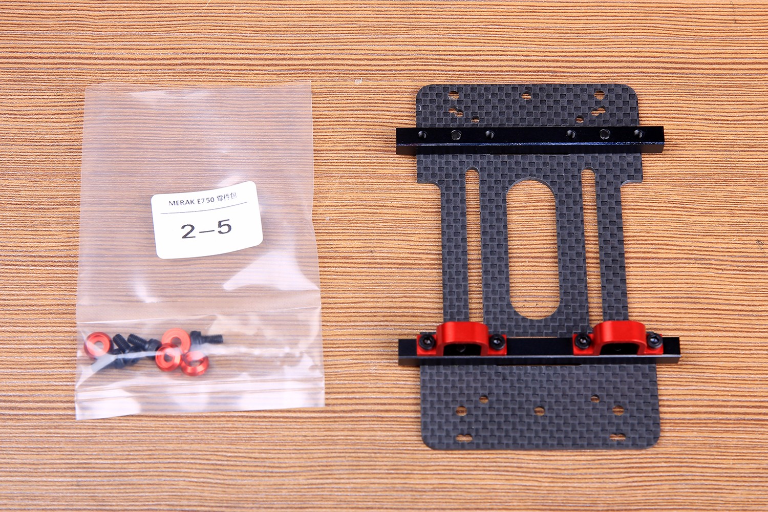
The installation height of the electric panel can be adjusted up and down, and the installation location should be selected according to their own needs.
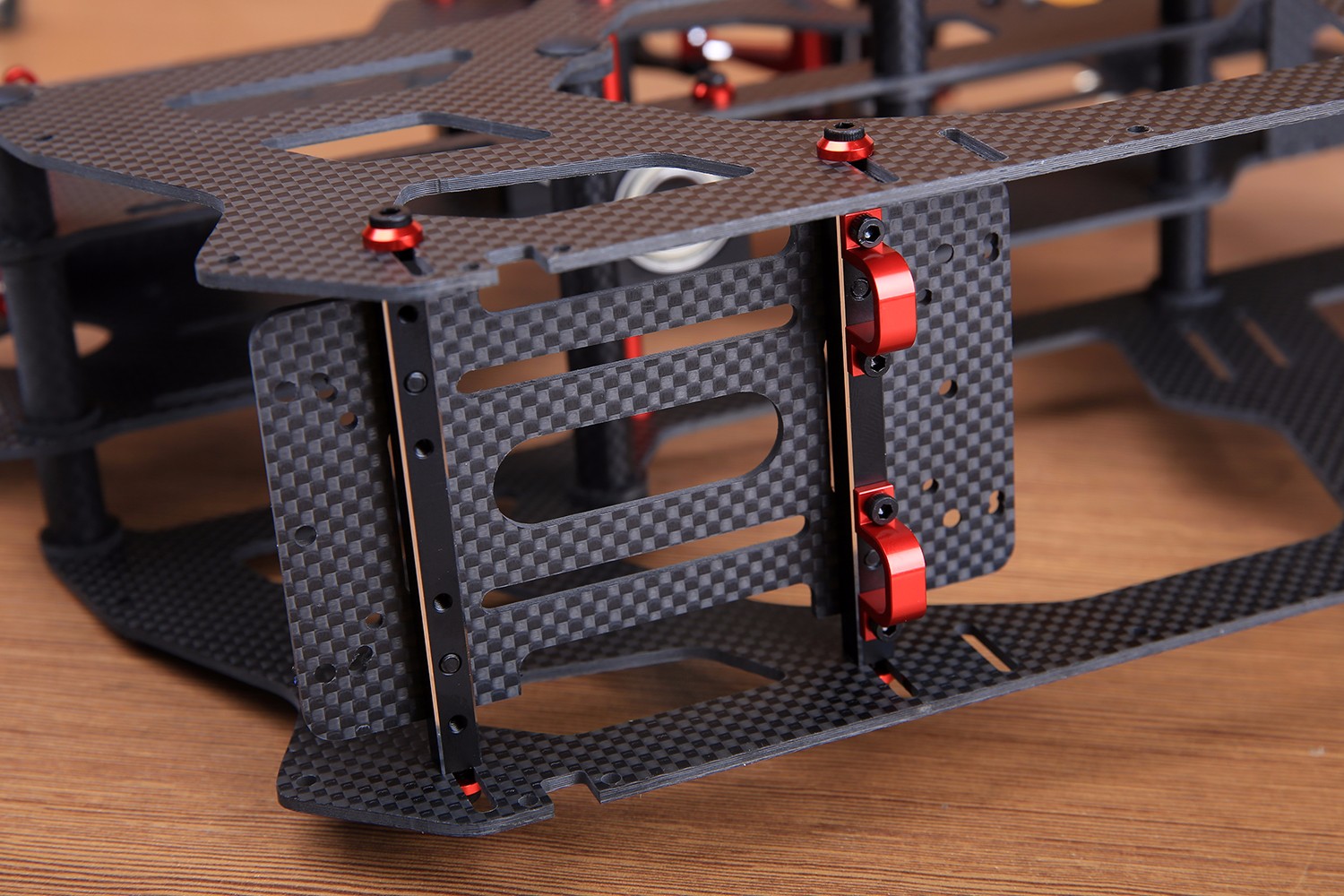

In the rear is to install the battery slide. Here we should pay attention to the most nose direction of the screws do not tighten, after the installation of a good scaffold fixed seat after the need to fine-tune the installation space of the battery plate.
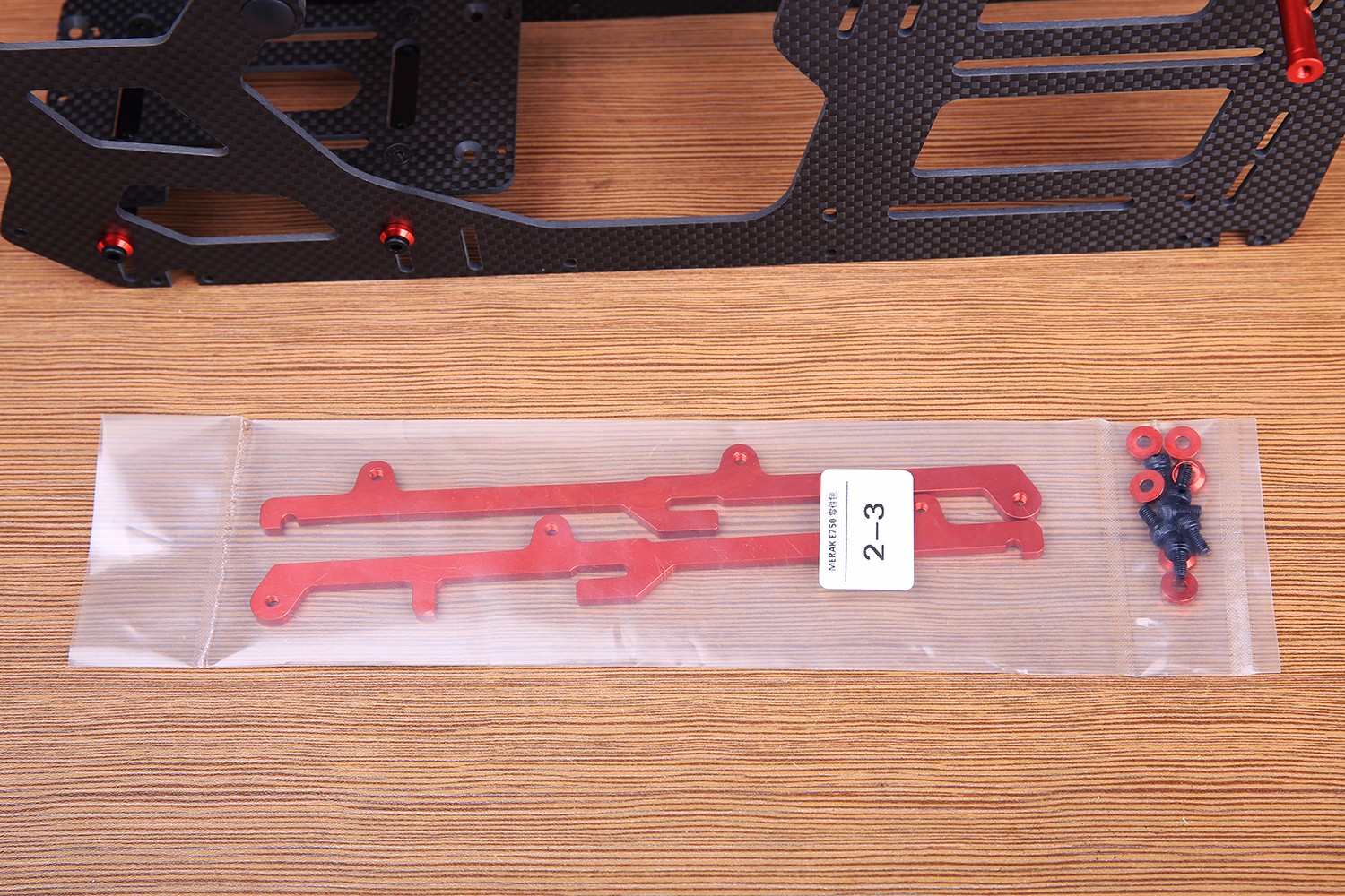
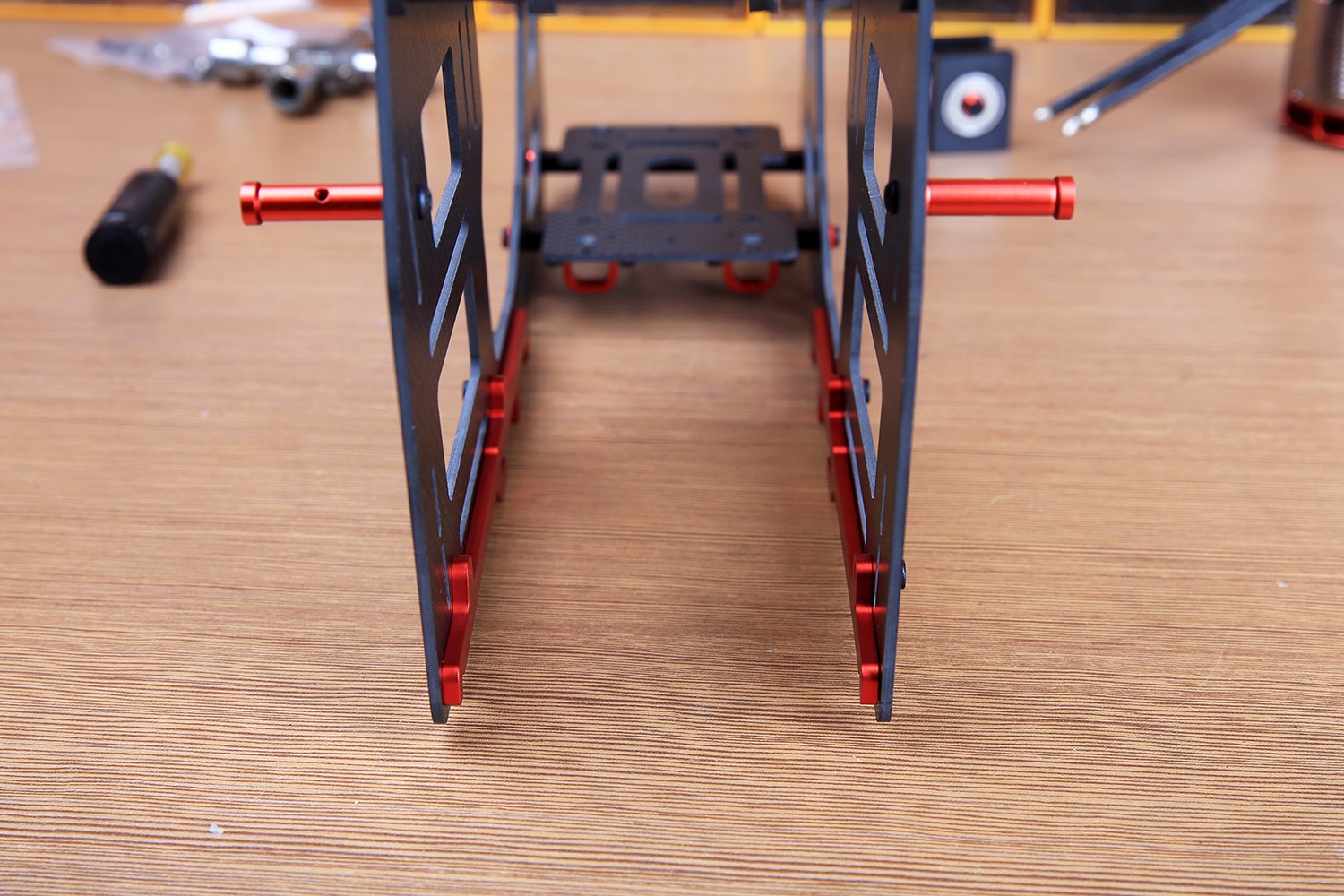

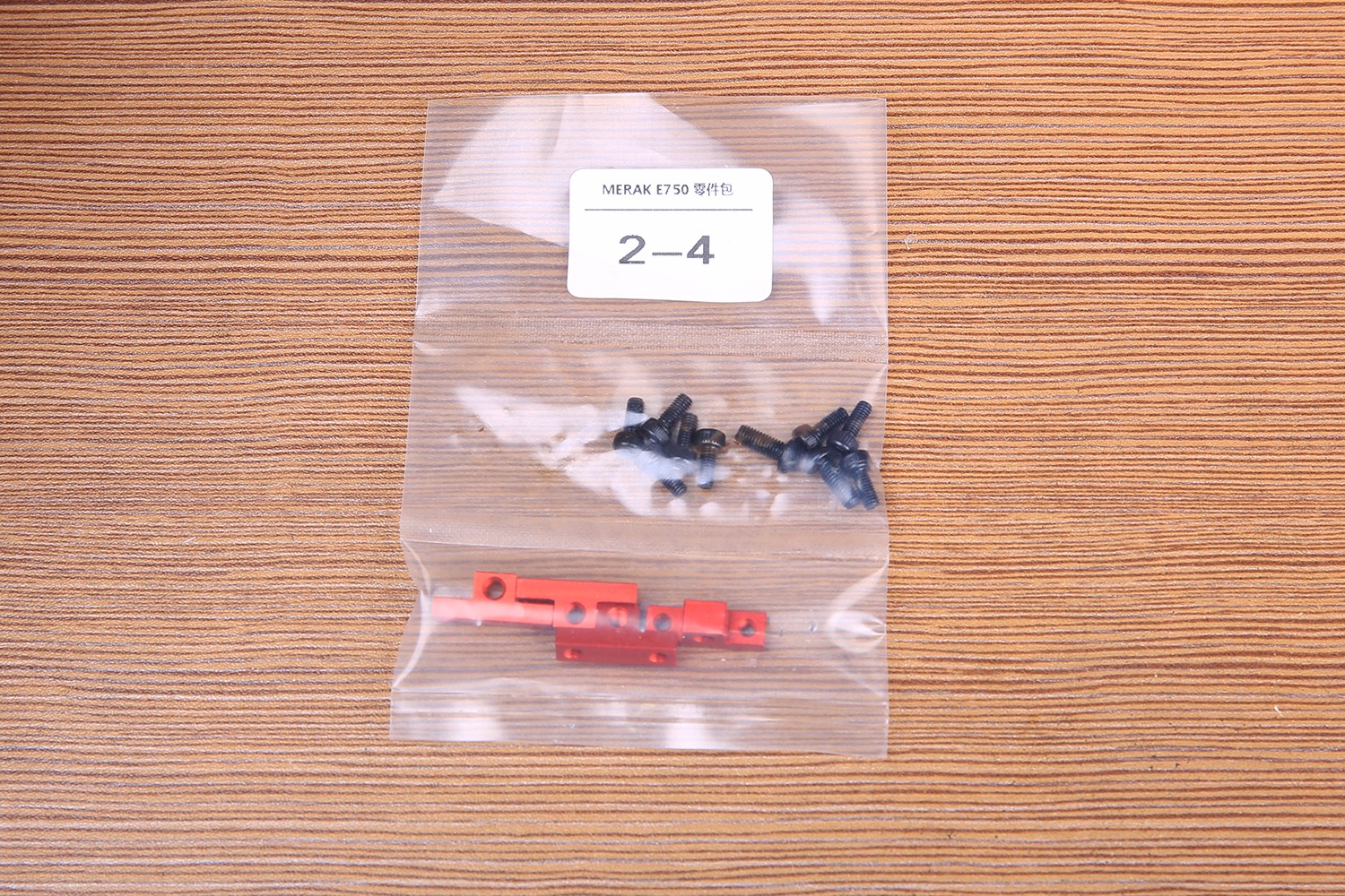
2-4 the main parts of the parts are the pedestal holders.
Screw the screws on the four corners of the side board with M2.5*6 screws.
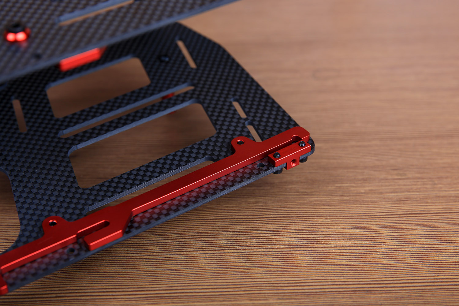
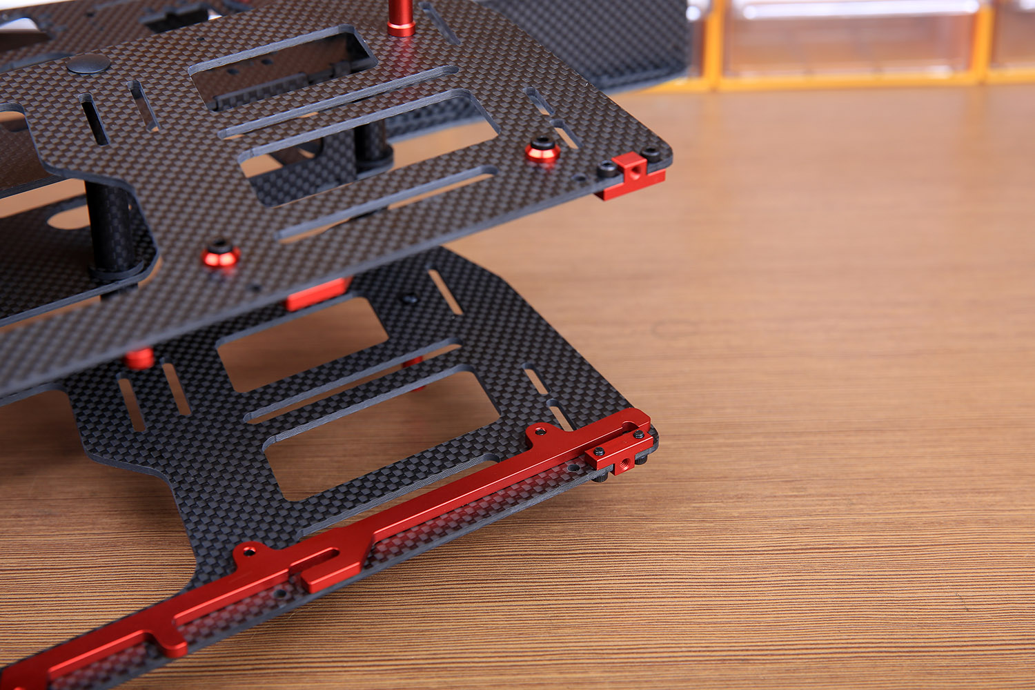
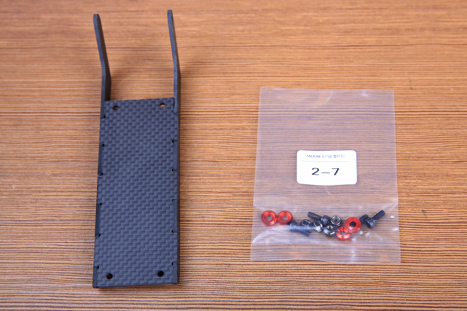
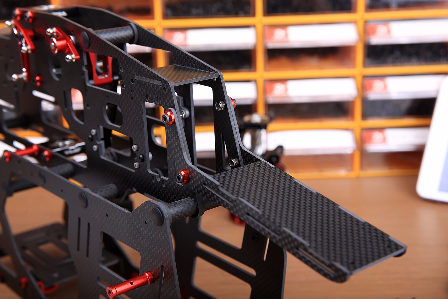
2-7 part package is used to install equipment rack, which can put battery, receiver and other equipment.
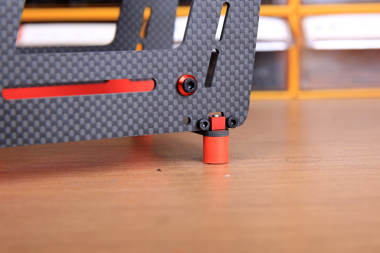
2-9零件包是脚架减震垫。
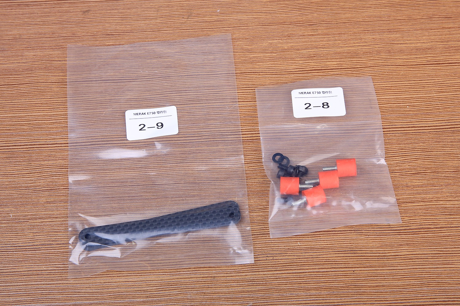
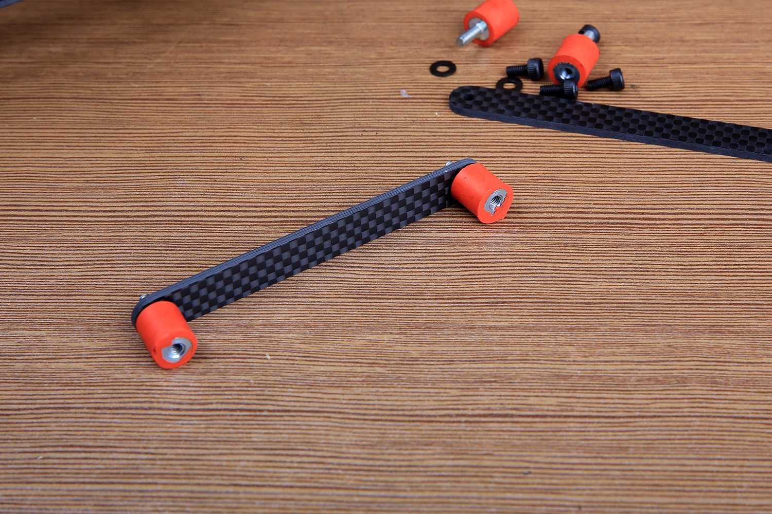
橡胶减震柱穿过碳板后固定在脚架固定座上。
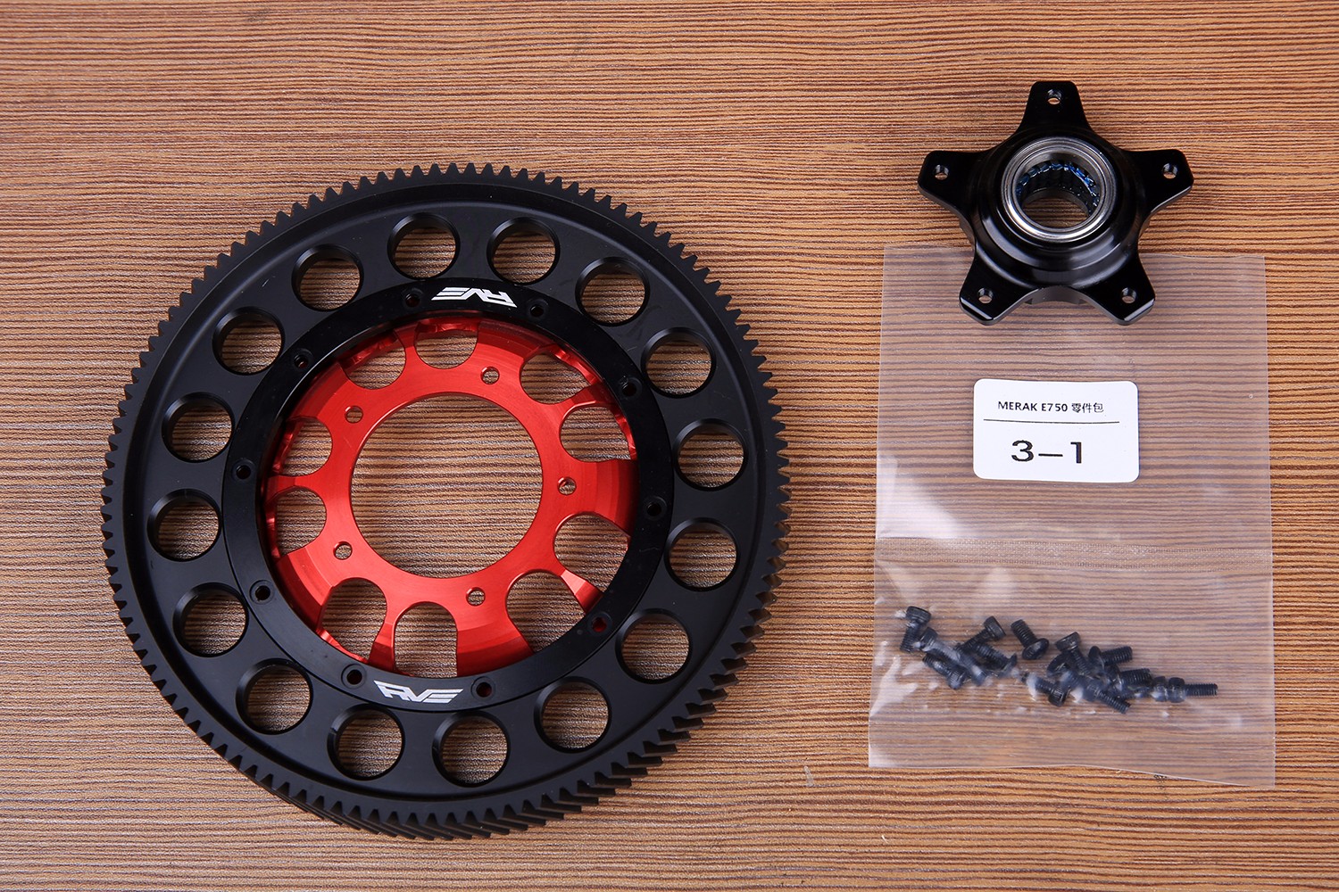
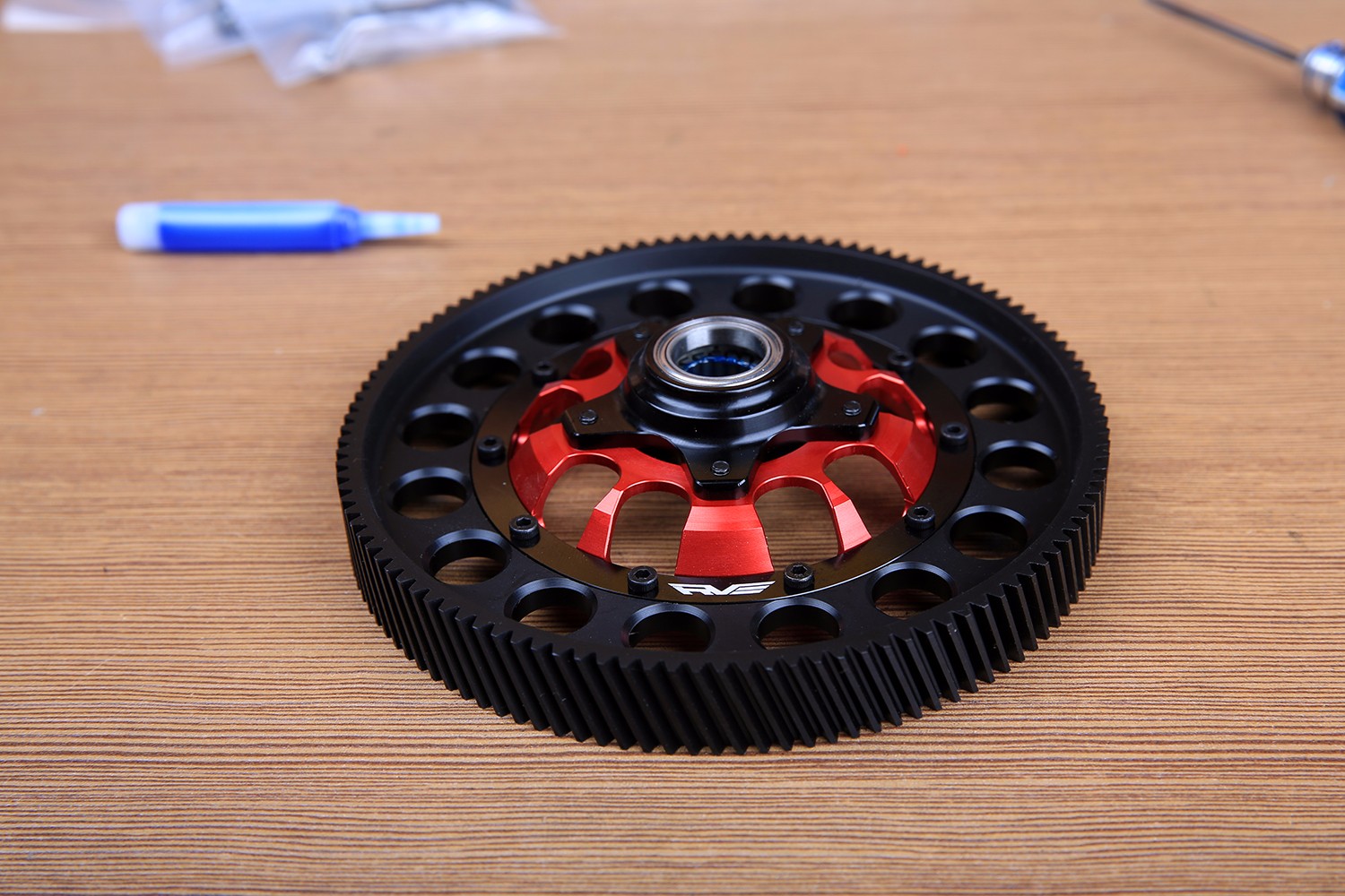
The big gear is made from DuPont bar in Japan, and its accuracy and intensity are very high. Take out the big gear, the single bearing seat and the 3-1 parts package.
First, the unidirectional bearing block and the main gear hub are fixed with M3*5 screws as shown below.
In order to ensure concentricity, the gear hub and the one-way bearing seat are tightly matched. When installed, the red gear hub can be heated by a wind gun and then sleeved into the one-way bearing seat. If it is cold matching, it needs to be pressed horizontally and hit in place evenly with a skin hammer.
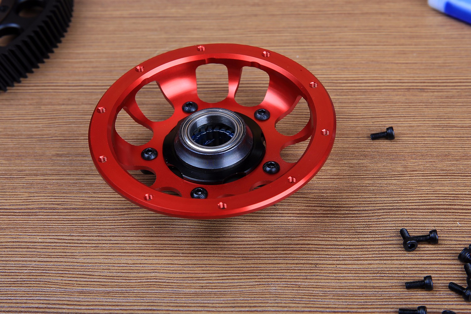
Please note the direction of unidirectional bearings and hub.
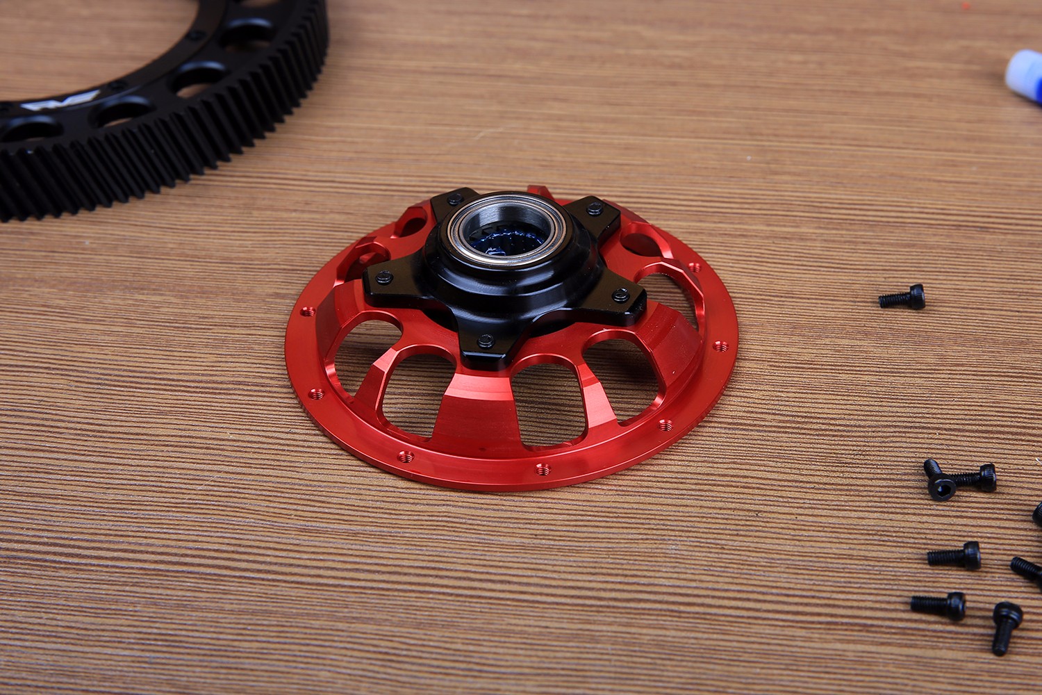
最后安装POM大齿盘,要注意10颗M2.5的锁紧螺丝一定要交叉对角均匀锁紧以免出现齿轮不平的现象。
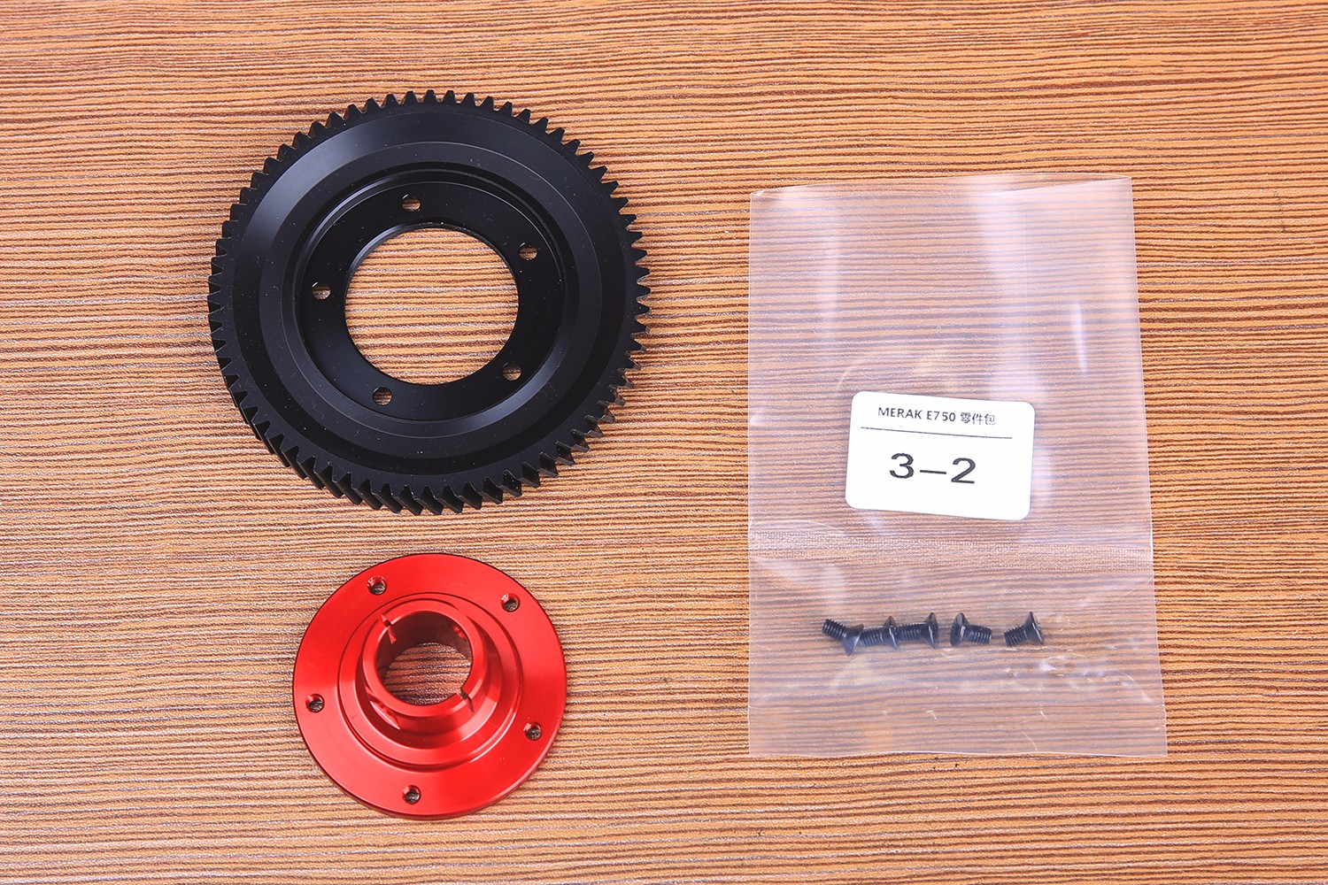
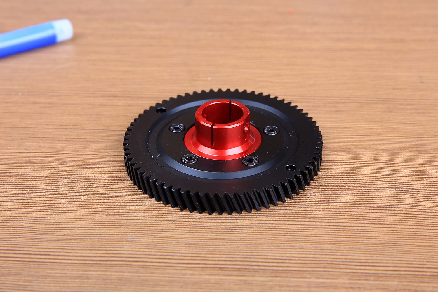
Drive gears and gear hubs are fixed with M3*8 countersunk head hexagonal, pay attention to uniform screw tightening to avoid gear deformation.
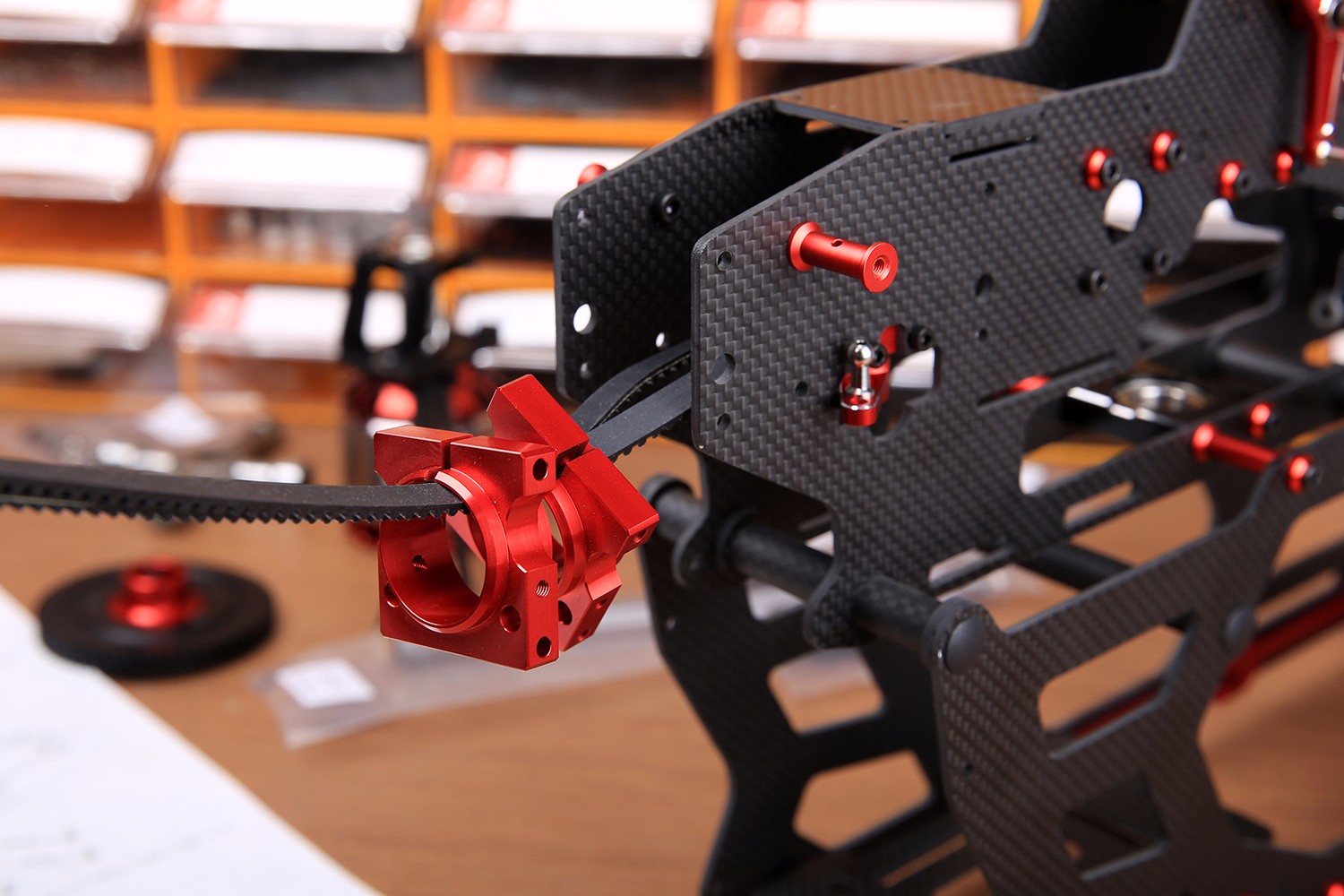
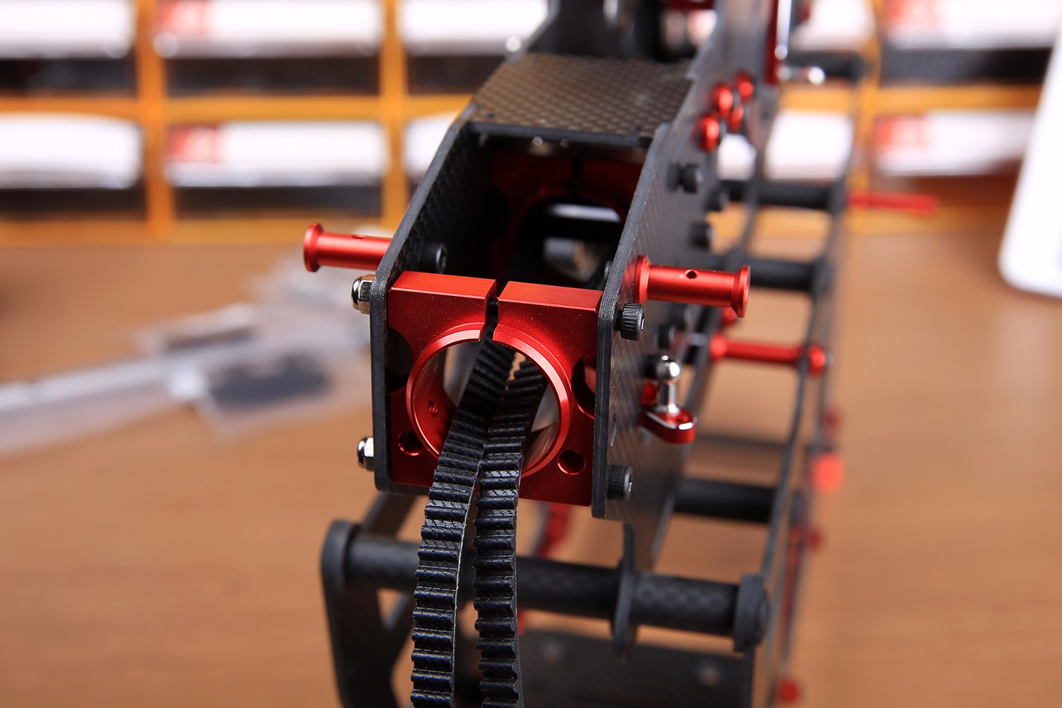
Next, we first put the belt through the body in this way.
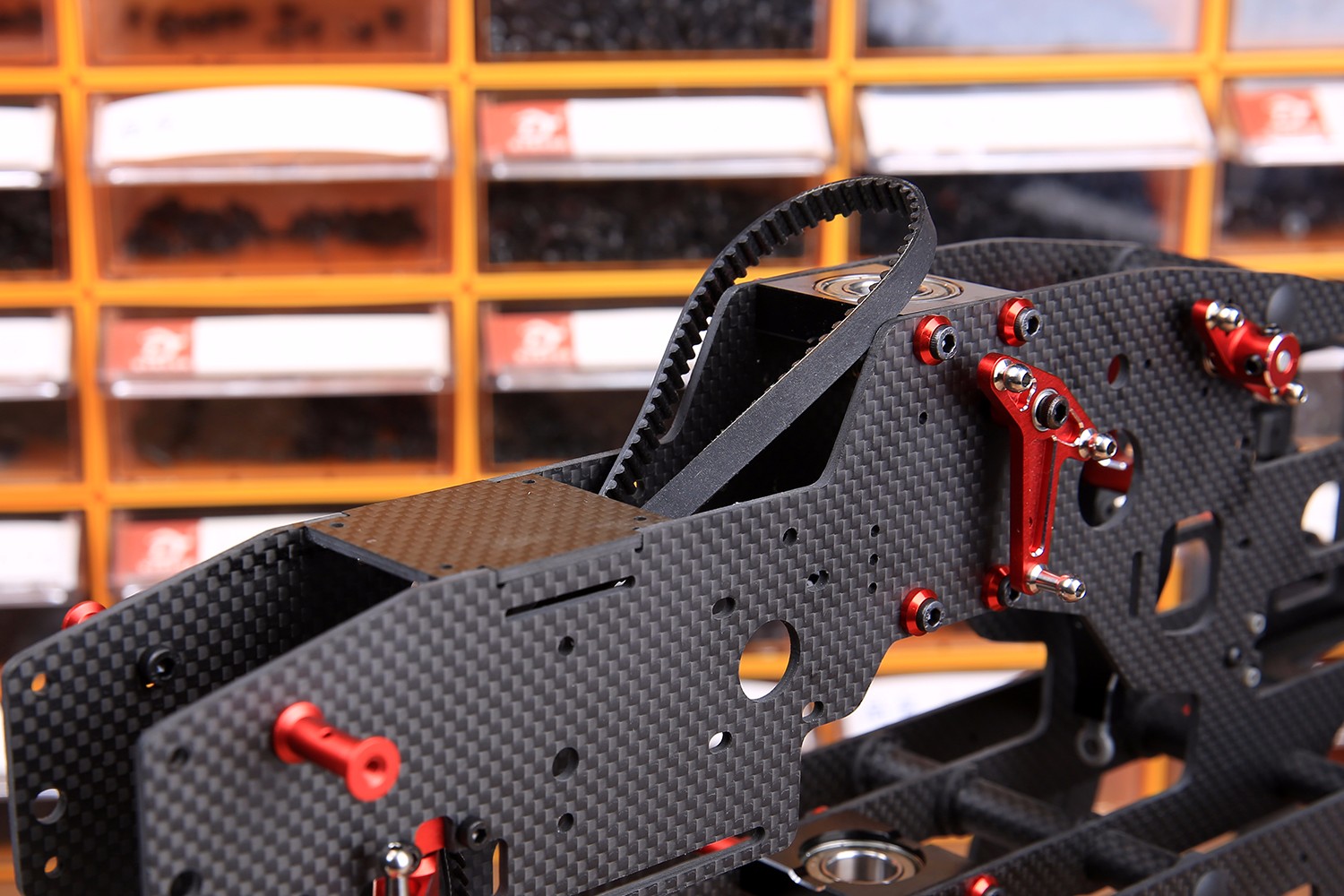
Install the rear drive gear housing that is assembled in place.
Do not tighten the screws after loading, wait for the big gear to be installed and adjust the gear clearance before fixing.
The tailpipe holder first passes through the belt and then is placed in the side plate.
取出安装好的电机组和3-4零件包,我们把电机也固定好。
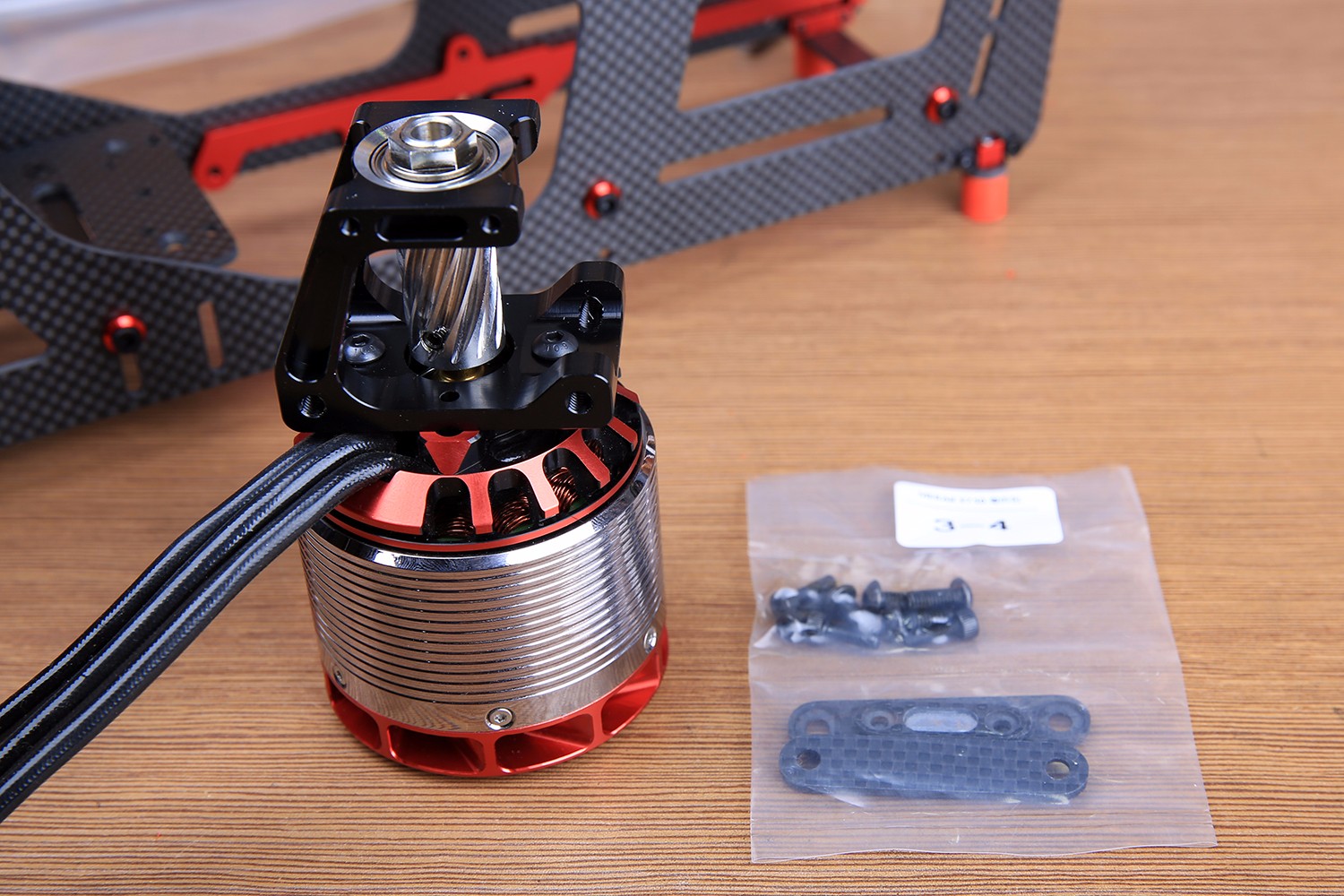
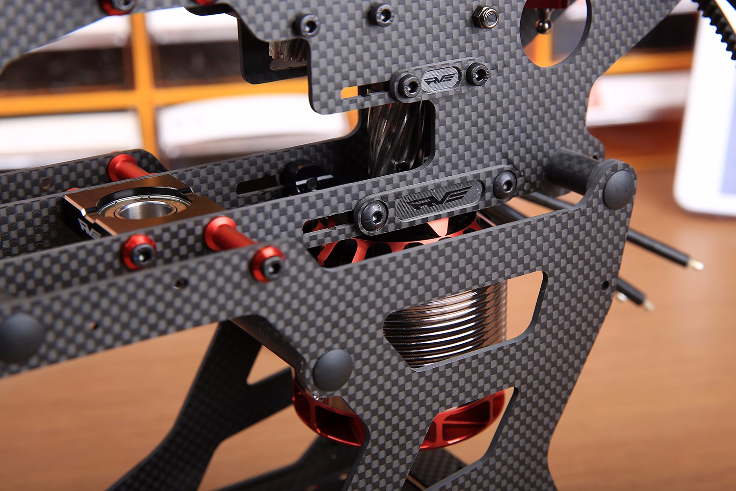
下面四颗M4*10的半圆头内六角固定,上面四颗M3*10螺丝。垫片不要忘记哦。
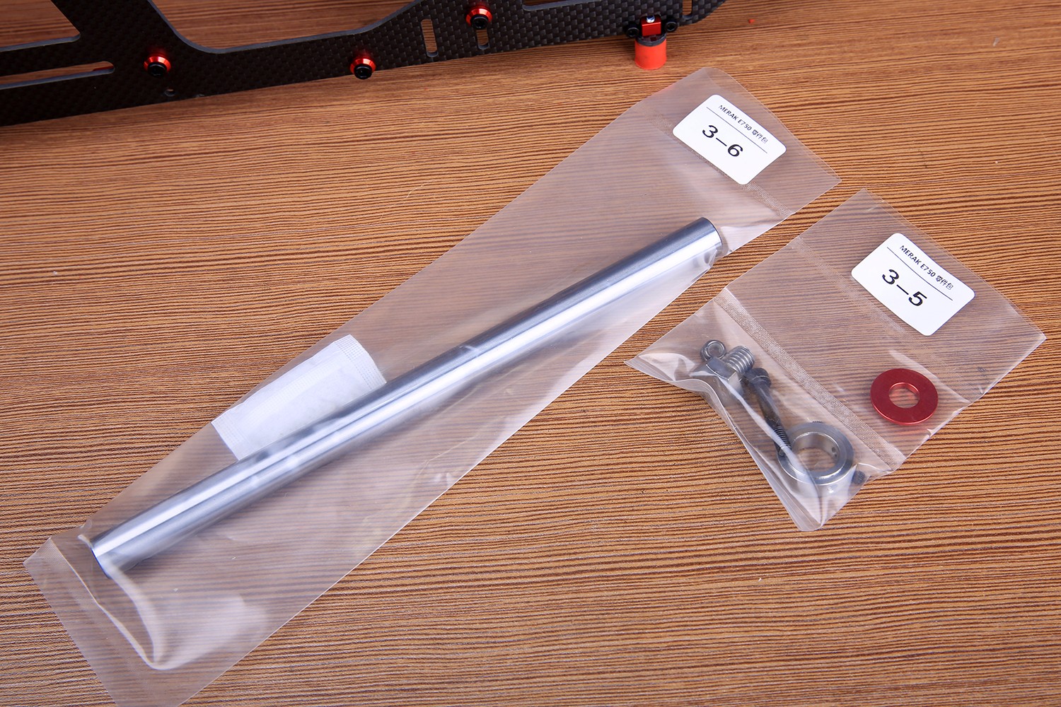
The 3-5 and 3-6 parts packages are removed below, which are fixed spindle and large gear.
下面取出3-5和3-6零件包,这部分是固定主轴和大齿轮的。
取出单向轴承内套、组装好的大小齿轮。
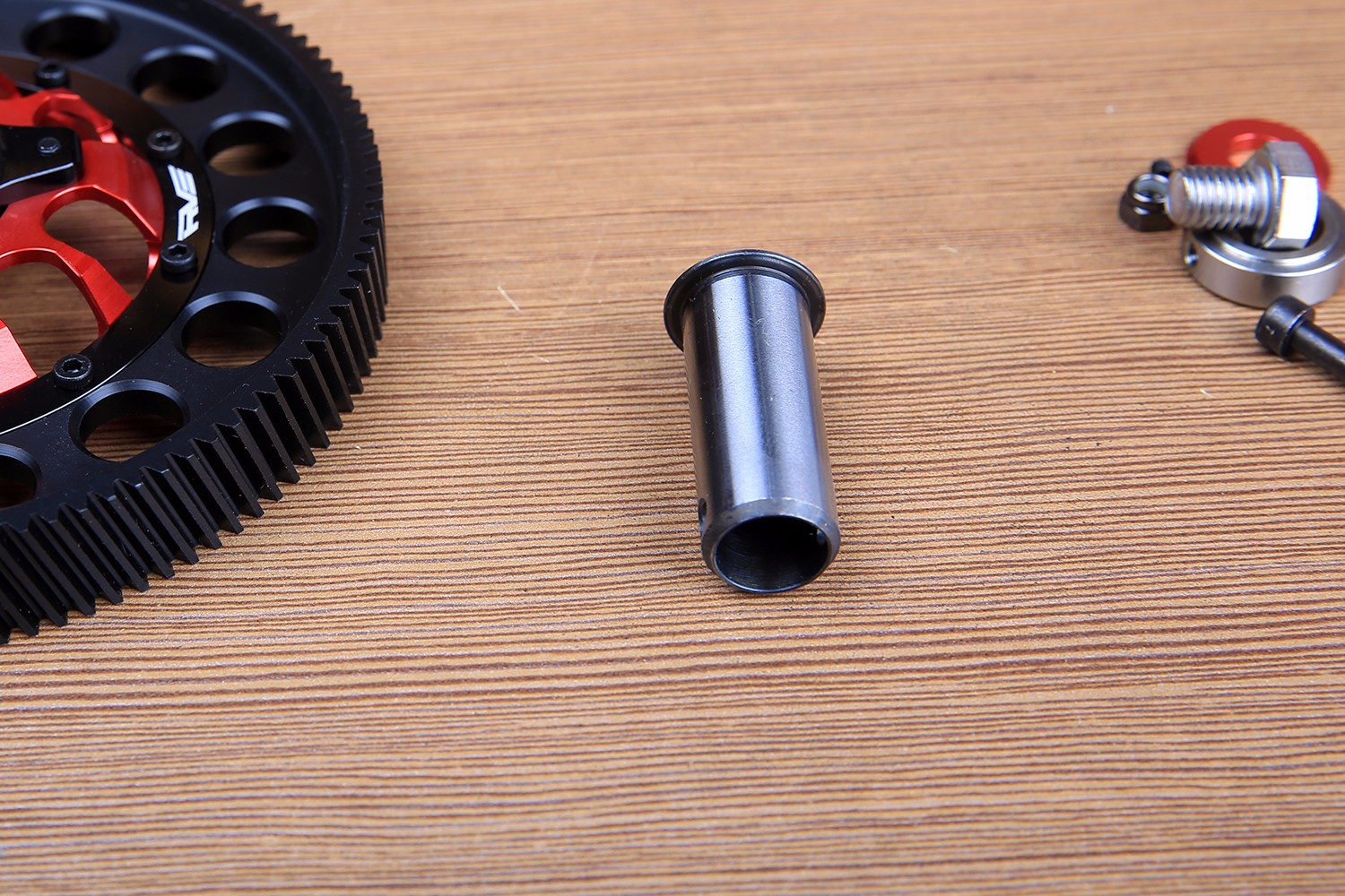
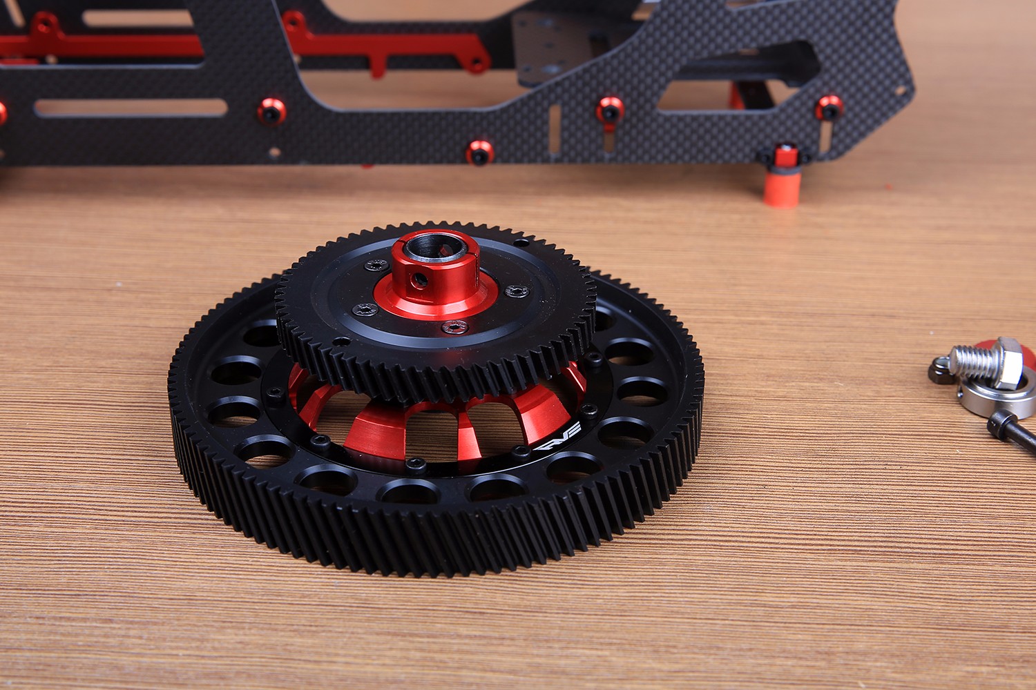
Put in the side panel, first align the screw holes.
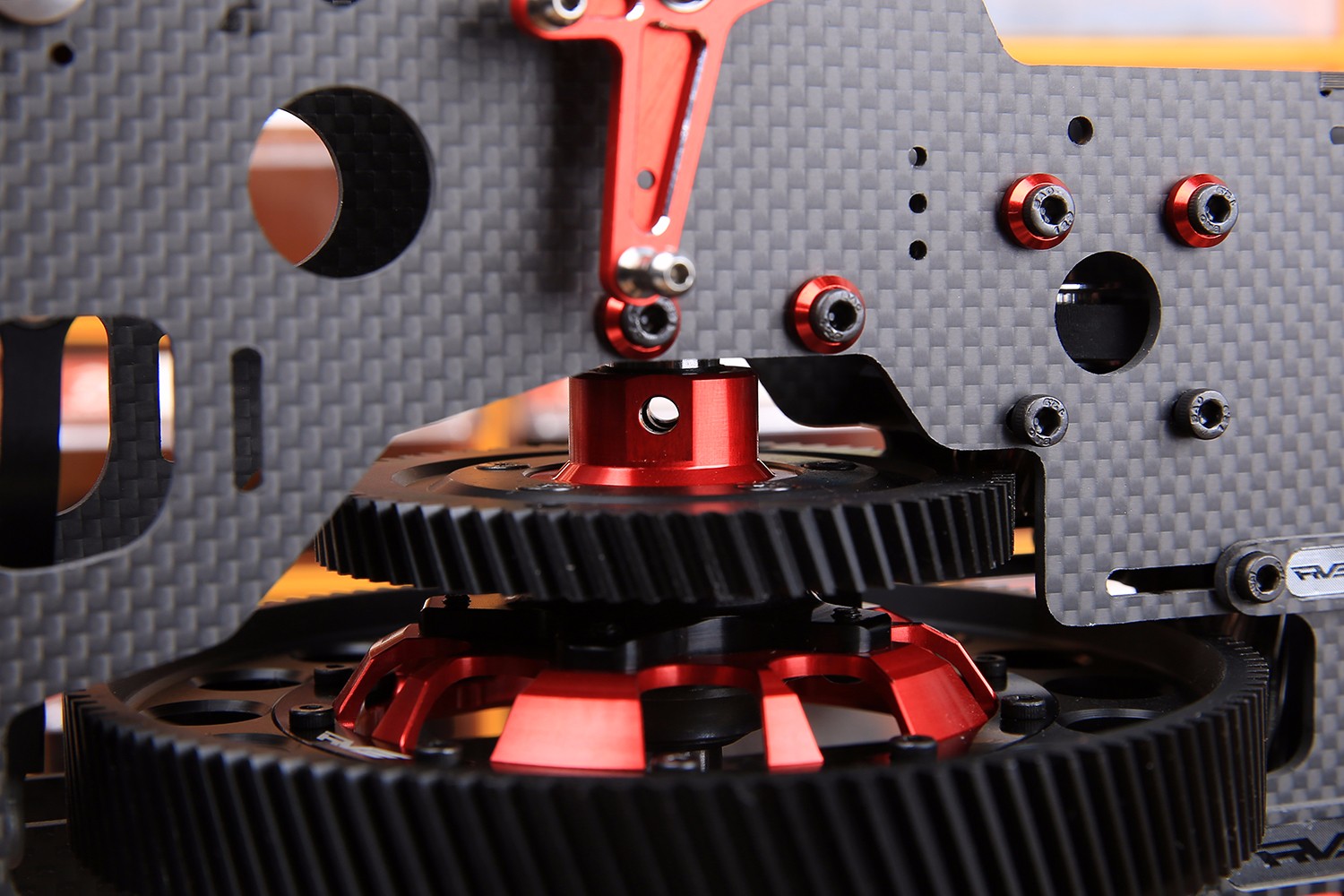
M4*24内六角螺丝穿过主轴拧紧固定大齿轮。
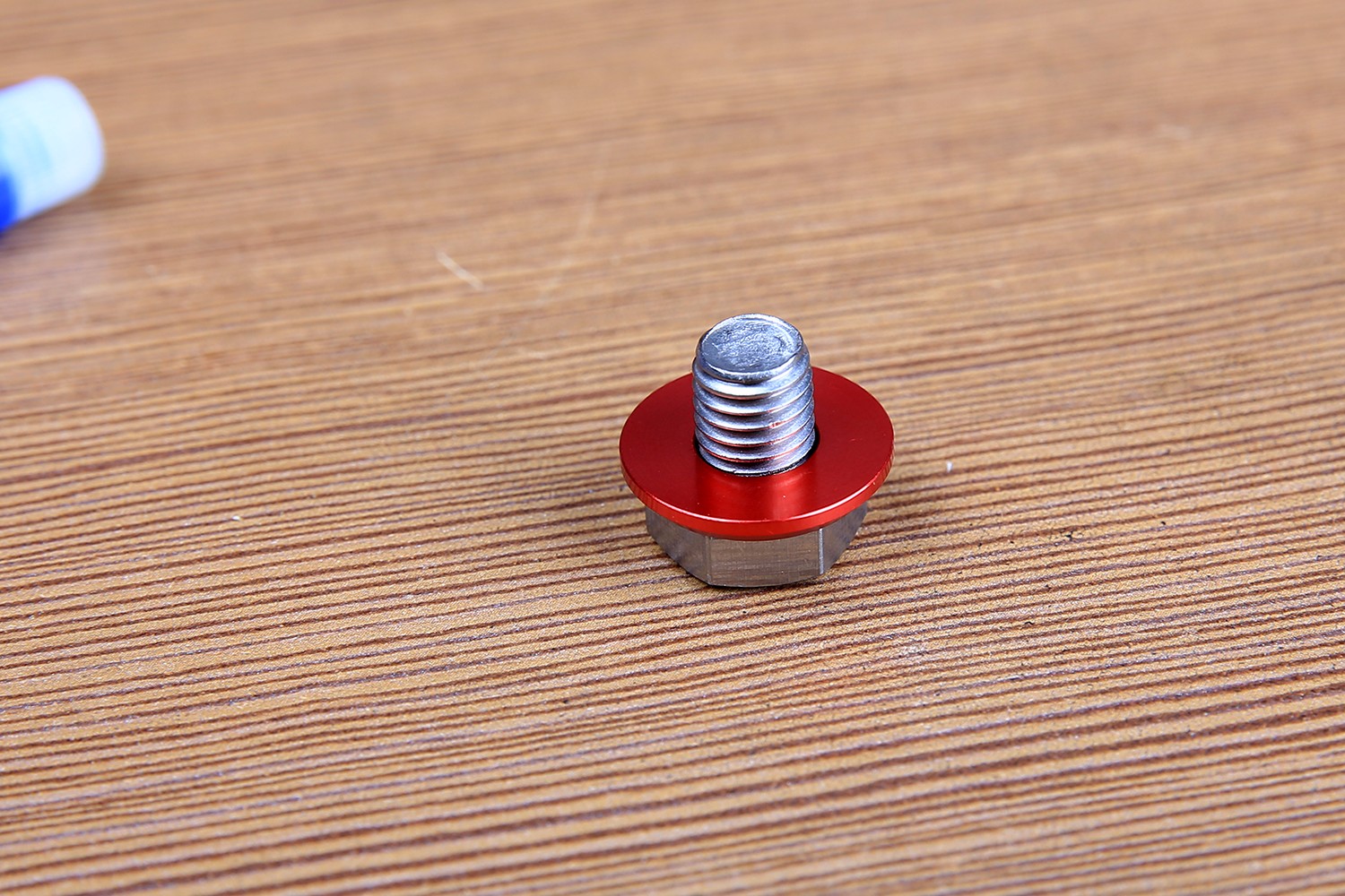
The outer six corner screws of the M8 are mounted on the bottom end of the spindle with gaskets. We need to tighten the blue screws.
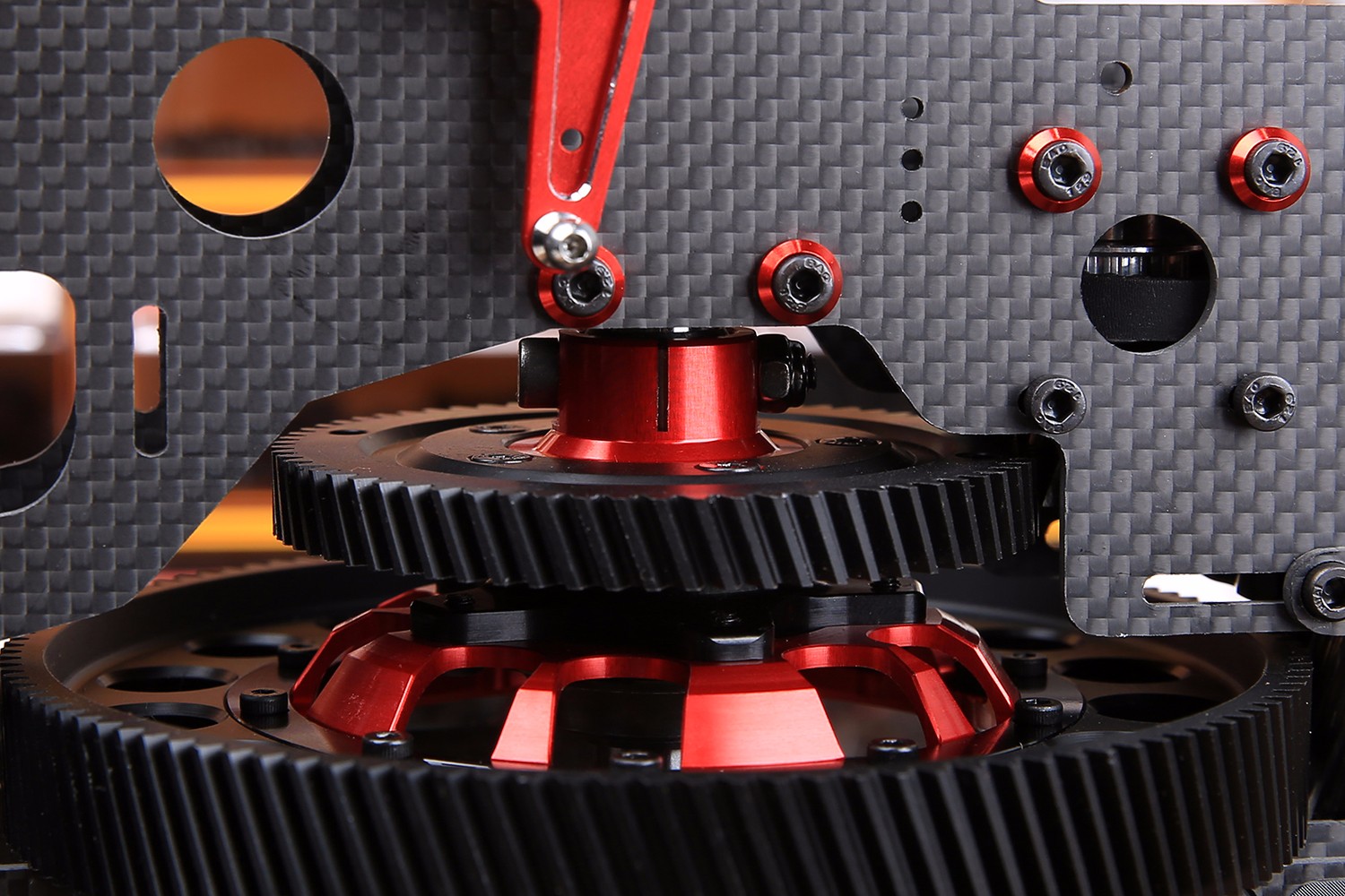
After fixing the outer six corner screws, the spindle retaining ring is penetrated from the spindle. Here we should pay attention to lift the spindle upward, then press down the positioning ring and tighten the top wire at the same time.
